Table of contents
General information 4
Inspection on receipt 6
Available accessories 7
Product description 8
Proper use 8
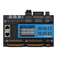
UMG 96RM-PN features 10
Measuring process 11
Operating concept 11
GridVis network analysis software 11
Connection variants 12
Assembly 13
Installation 15
Supply voltage 15
Voltage measurement 16
Current measurement using I1 to I4 22
Analogue inputs 30
Residual current monitoring (RCM) via I5, I6 31
Thermistor input 33
RS485 interface 34
Ethernet / ProfiNet interface 37
Digital in-/outputs 39
LED status bar 44
Operation 45
Display mode 45
Programming mode 45
Parameters and measured values 47
Configuration 49
Connecting the supply voltage 49
Current and voltage transformer 49
Programming the current transformer for I1-I3 51
Programming the voltage transformer 52
Programming parameters 53
TCP/IP configuration 54
RS485 device address (addr. 000) 56
RS485 baud rate (addr. 001) 56
User password (addr. 050) 57
Parameters 58
Mean value 58
Averaging method 58
Min. and max. values 58
Mains frequency (addr. 034) 59
Power meters 60
Resetting energy meters (addr. 507) 60
Harmonics 61
Measured value rotation 62
Measured value screens 62
Direction of the rotating field 64
LCD contrast (addr. 035) 64
Backlight 64
Time logging 66
Operating hours counter 66
Total running time, comparator 66

 Loading...