AAA-055-00188
Jaylor Owner Manual -21- 5000 Series Truck Mount Models
15. CONTROLS
Weighing
15.1.1 Scale System Overview
• The scale system on all models includes 4 weigh-bars. The weigh-bars electronically measure the
amount of ration inside the mixing chamber.
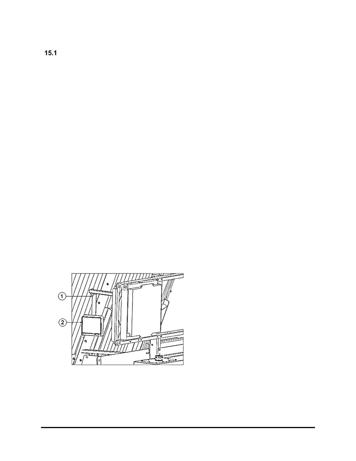
15.1.2 Indicator Mounting and Adjustment
• There are various scale indicators available for use on your Jaylor however the mounting assembly
for most scale indicators is the same. When attaching the indicator to the machine, be sure that it is
securely fastened. Typically, the indicator slides down into the mounting bracket and a wire or plastic
fastener is used to secure the indicator to the mounting bracket.
• To adjust the direction of the indicator display face, see Figure 7.
15.1.3 Indicator Connections
• On the bottom of the indicator are outlets for attaching the weigh-bar cords. These should not be
confused with the power supply, which will not attach in the same outlet. The weigh-bar cords are
pushed in and then the tightening ring is threaded into place. Make sure that the plugs are free of
moisture or other contaminants as this will affect the performance of the weighing system.
• Typically, the mixer weigh-bars are plugged into a junction bar and then a single line is run into the
scale head in the cab. The power cord is run to a power connection in the cab from the vehicle’s
electrical system. This should be a 12-volt negative grounded power supply.
15.1.4 Remote Indicator (Optional)
• This indicator is usually placed such that it can be viewed from the loading equipment. In most cases
the remote indicator does not allow full access to weigh system parameters. These parameters are
controlled from the main indicator as described earlier. The remote indicator attaches to the main
indicator via a cable or wirelessly. Like all of the other connections, ensure the plugs are free from
moisture and other contaminants as this will affect the performance of the weighing system.
1. Swivel Joint – Swivel joint lock nut
should be snug enough to hold the
indicator in position but not too tight to
be turned by hand. The indicator can
then be rotated to face any direction.
2. Scale Indicator
Note:
• The scale will be programmed to display weight in either kilograms (kg) or pounds (lbs). If your scale
is not programmed to your preferred units of measurement, or for any other settings, please see the
manual which has been provided by the scale system manufacturer.