EasyManua.ls Logo

JBL MS-8 - Pins Description; Pins Connection Diagram of the Flexiwatt27 (Top of View); Pins Connection Diagram of the Powerso36 Slug up (Top of View)

JBL MS-8
110 pages
Print Icon
To Next Page IconTo Next Page
To Previous Page IconTo Previous Page
Loading...
TDA7563B Pins description
7/33
2 Pins description
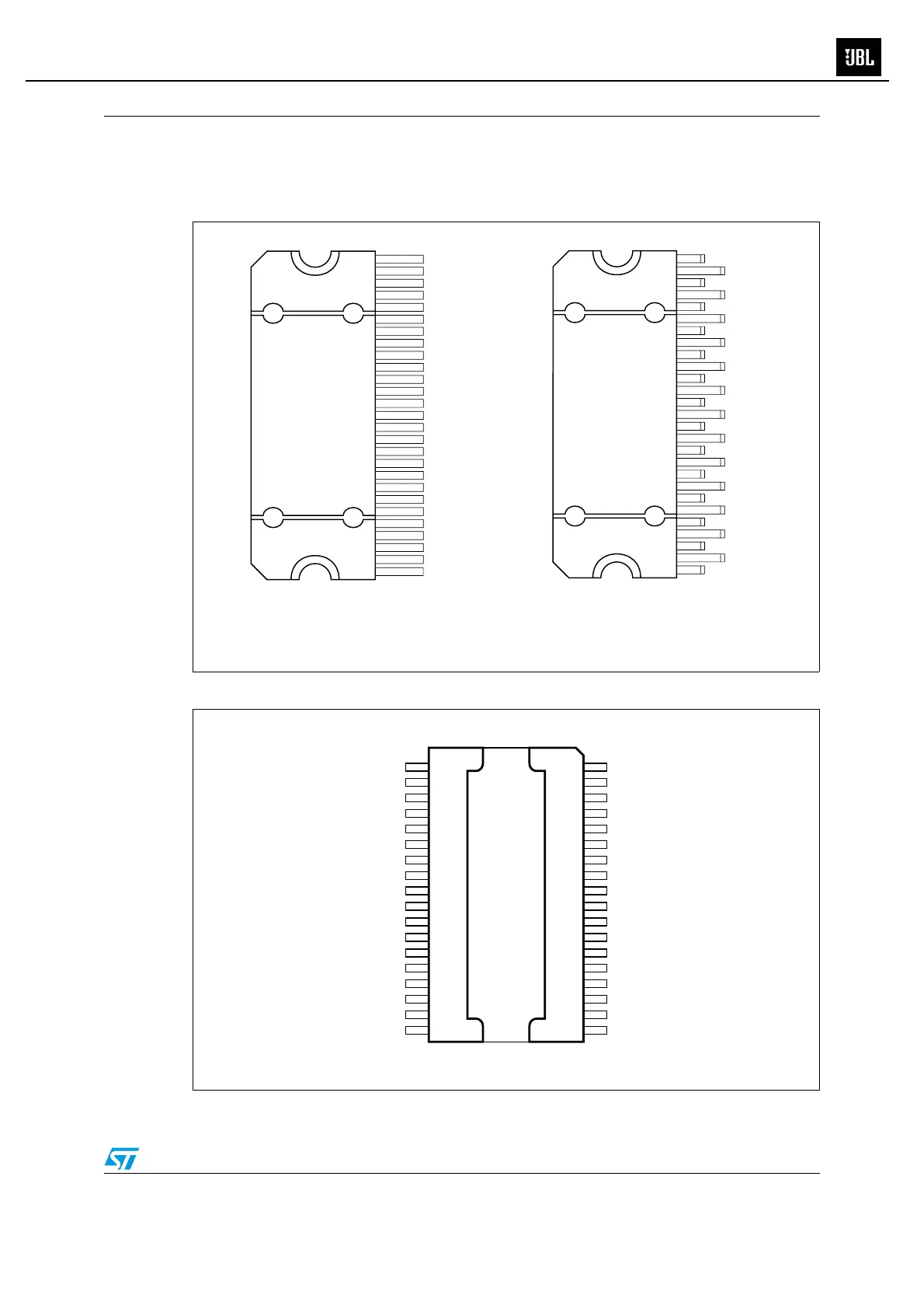
Figure 3. Pins connection diagram of the Flexiwatt27 (top of view)
Figure 4. Pins connection diagram of the PowerSO36 slug up (top of view)
D00AU123
0
TAB
STBY
PW_GND LR
OUT LR-
CD-OUT
OUT LR+
V
CC1
OUT LF-
PW_GND LF
OUT LF+
SVR
IN LF
IN LR
S_GND
IN RR
IN RF
AC GND
OUT RF+
PW_GND RF
OUT RF-
V
CC2
CK
OUT RR-
OUT RR+
PW_GND RR
DATA
TAB
1
2
3
4
5
6
7
8
9
10
11
12
13
14
15
16
17
18
19
20
25
26
22
21
23
24
27
D00AU141
6
TAB
STBY
PW_GND LR
OUT LR-
CD-OUT
OUT LR+
V
CC1
OUT LF-
PW_GND LF
OUT LF+
SVR
IN LF
IN LR
S_GND
IN RR
IN RF
AC GND
OUT RF+
PW_GND RF
OUT RF-
V
CC2
CK
OUT RR-
OUT RR+
PW_GND RR
DATA
TAB
1
2
3
4
5
6
7
8
9
10
11
12
13
14
15
16
17
18
19
20
25
26
22
21
23
24
27
Flexiwatt27 (vertical)
Flexiwatt27 (horizontal)
CD
N.C.
N.C.
OUT2+
PWGND
OUT4+
N.C.
N.C.
CKOUT3-
N.C.
N.C.
OUT3+
PWGND
PWGND
N.C.
OUT1-
VCC 18
16
17
15
6
5
4
3
2
21
22
31
32
33
35
34
36
20
1
19
TABVCC
D04AU1547A
OUT4-
VCC
DATA
ACGND
IN4
IN3
9
8
7
28
29
30
OUT2-SGND 1027
N.C.
STBY
VCC
IN2
OUT1+
IN1
14
12
11
23
25
26
PWGNDSVR 1324
MS-8
67

Table of Contents

Other manuals for JBL MS-8

Related product manuals