Philips Semiconductors Pr
oduct specification
Dual 4-channel analog multiplexer,
demultiplexer
74HC4052; 74HCT4052
FEATURES
• Wide analog input voltage range from −5 V to +5 V
• Low ON-resistance:
–80Ω (typical) at V
CC
− V
EE
= 4.5 V
–70Ω (typical) at V
CC
− V
EE
= 6.0 V
–60Ω (typical) at V
CC
− V
EE
= 9.0 V
• Logic level translation: to enable 5 V logic to
communicate with ±5 V analog signals
• Typical “break before make” built in
• Complies with JEDEC standard no. 7A
• ESD protection:
– HBM EIA/JESD22-A114-B exceeds 2000 V
– MM EIA/JESD22-A115-A exceeds 200 V.
• Specified from −40 °C to +85 °C and −40 °C to +125 °C.
APPLICATIONS
• Analog multiplexing and demultiplexing
• Digital multiplexing and demultiplexing
• Signal gating.
DESCRIPTION
The 74HC4052 and 74HCT4052 are high-speed Si-gate
CMOS devices and are pin compatible with the
HEF4052B. They are specified in compliance with JEDEC
standard no. 7A.
The 74HC4052 and 74HCT4052 are dual 4-channel
analog multiplexers or demultiplexers with common select
logic. Each multiplexer has four independent
inputs/outputs (pins nY0 to nY3) and a common
input/output (pin nZ). The common channel select logics
include two digital select inputs (pins S0 and S1) and an
active LOW enable input (pin
E). When pin E = LOW, one
of
the four switches is selected (low-impedance ON-state)
with pins S0 and S1. When pin
E = HIGH, all switches are
in
the high-impedance OFF-state, independent of pins S0
and S1.
V
CC
and GND are the supply voltage pins for the digital
control inputs (pins S0, S1, and
E). The V
CC
to GND
ranges are 2.0 V
to 10.0 V for 74HC4052 and
4.5 V to 5.5 V for 74HCT4052. The analog inputs/outputs
(pins nY0 to nY3 and nZ) can swing between V
CC
as a
positive limit and V
EE
as a negative limit. V
CC
− V
EE
may
not exceed 10.0 V.
For operation as a digital multiplexer/demultiplexer, V
EE
is
connected to GND (typically ground).
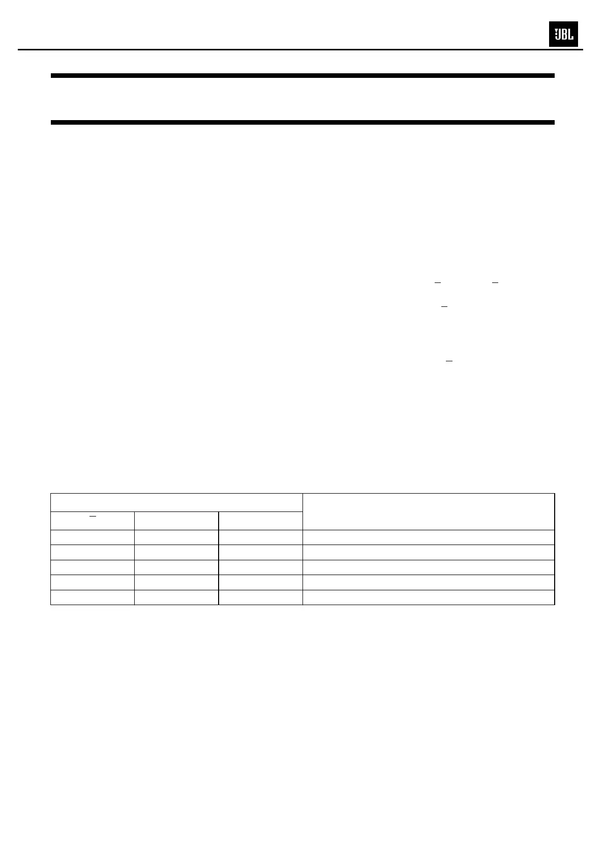
FUNCTION TABLE
Note
1. H = HIGH voltage level
L = LOW voltage level
X = don’t care.
INPUT
(1)
CHANNEL BETWEEN
ES1
S0
L L L nY0 and nZ
L L H nY1 and nZ
L H L nY2 and nZ
L H H nY3 and nZ
H X X none
MS-8