Philips Semiconductors Product specification
Dual 4-channel analog m
ultiplexer,
demultiplexer
74HC4052; 74HCT4052
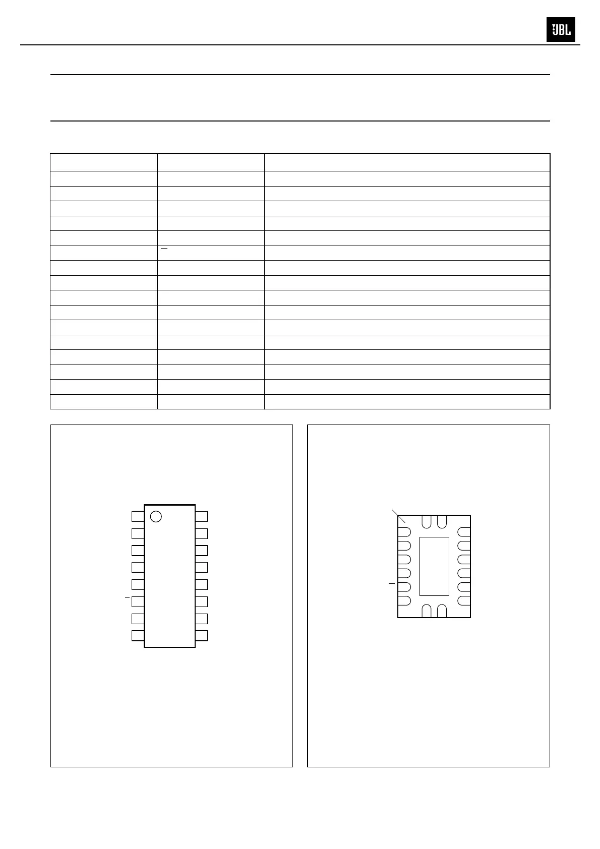
PINNING
PIN SYMBOL DESCRIPTION
1 2Y0 independent input or output
2 2Y2 independent input or output
3 2Z common input or output
4 2Y3 independent input or output
5 2Y1 independent input or output
6
E enable input (active LOW)
7V
EE
negativ
e supply voltage
8 GND ground (0 V)
9 S1 select logic input
10 S0 select logic input
11 1Y3 independent input or output
12 1Y0 independent input or output
13 1Z common input or output
14 1Y1 independent input or output
15 1Y2 independent input or output
16 V
CC
positive supply voltage
handbook, halfpage
4052
MNB039
1
2
3
4
5
6
7
8
16
15
14
13
12
11
10
9
2Y0
2Y2
2Z
2Y3
2Y1
E
V
EE
GND
S1
S0
1Y3
1Y0
1Z
1Y1
1Y2
V
CC
Fig.1 Pin configuration DIP16, SO16 and
(T)SSOP16. Fig.2 Pin configuration DHVQFN16.
(1)
The die substrate is attached to this pad using conductive die
attach material. It can not be used as a supply pin or input.
001aac117
4052
V
CC
(1)
V
EE
S0
E 1Y3
2Y1 1Y0
2Y3 1Z
2Z 1Y1
2Y2 1Y2
GND
S1
2Y0
V
CC
Transparent top view
7 10
6 11
5 12
4 13
3 14
2 15
8
9
1
16
terminal 1
index area
MS-8