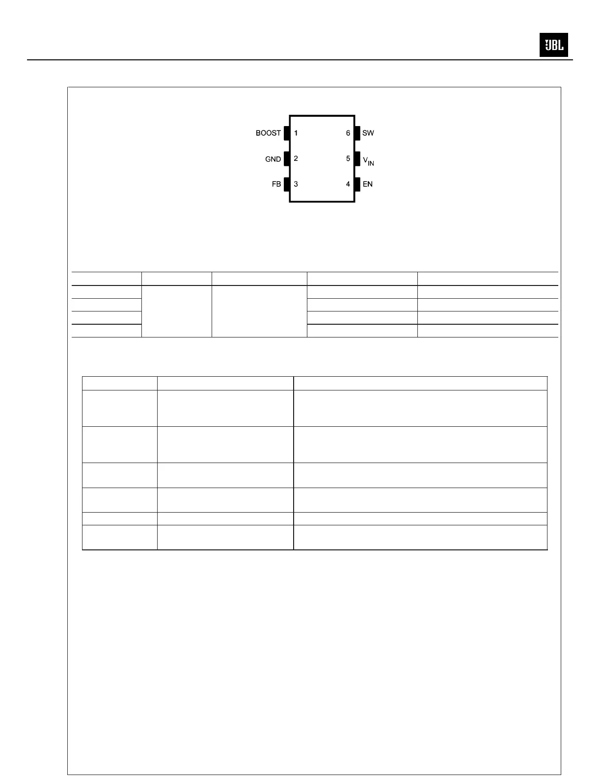
Connection Diagram
20102305
6-Lead TSOT
NS Package Number MK06A
Ordering Information
Order Number Package Type NSC Package Drawing Package Marking Supplied As
LM2734XMK
TSOT-6 MK06A
SFDB 1000 Units on Tape and Reel
LM2734YMK SFEB 1000 Units on Tape and Reel
LM2734XMKX SFDB 3000 Units on Tape and Reel
LM2734YMKX SFEB 3000 Units on Tape and Reel
* Contact the local sales office for the lead-free package.
Pin Description
Pin Name Function
1 BOOST Boost voltage that drives the internal NMOS control switch. A
bootstrap capacitor is connected between the BOOST and SW
pins.
2 GND Signal and Power ground pin. Place the bottom resistor of the
feedback network as close as possible to this pin for accurate
regulation.
3 FB Feedback pin. Connect FB to the external resistor divider to set
output voltage.
4 EN Enable control input. Logic high enables operation. Do not allow
this pin to float or be greater than V
IN
+ 0.3V.
5V
IN
Input supply voltage. Connect a bypass capacitor to this pin.
6 SW Output switch. Connects to the inductor, catch diode, and
bootstrap capacitor.
LM2734
www.national.com 2
MS-8
 Loading...