42 - 4
Drive Head Limited Slip Differential -
Assembly
The outline procedure below refers also to the following
aspects of the drivehead assembly, which are covered
separately in detail as sub topics later in this section:
Pinion Depth Setting
Collapsible Spacer Assembly
Crown Wheel and Pinion Meshing
Both the crownwheel 10 and pinion 23, and the side gears 15
and planet gears 13 are matched and should be renewed as
sets if any of their components are damaged or excessively
worn.
Make sure all bearings are lightly oiled before fitting and
setting. Make sure bearings are rotated whilst being set.
1 Fit side gears 15, with pressure plates 19, counter
plates 17 and friction plates 18 into differential case 8.
Note: Do not fit the shims 16 at this point.
Position planet gears 13 and thrust washers 14 until
they are engaged with side gears and diametrically
opposed. Rotate side gears until planet gears and
washers align with trunnion pin bore.
2 Drive in trunnion pin 12 until bolt 11 can be located.
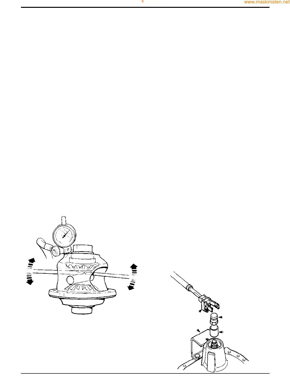
3 Using a dial test indicator, with two screwdrivers or
suitable levers, gently apply pressure to side gear 15
away from the trunnion pins 12 as shown. Measure and
note the end-float of the side gear.
4 Turn the differential assembly over and repeat step 3
for the second side gear.
5 Dismantle the differential assembly. Add shims 16 to
give end-float between 0.1 and 0.2mm (0.004 and
0.008in.).
Note: Shimming must be carried out whenever the
differential is dismantled, however the end float 0.1 and 0.2
mm (0.004 and 0.008 in.) can be exceeded on previously
assembled differential as this is only an initial setting figure
which allows for bedding in.
6 Repeat steps 2, 3, and 4. If the end float is correct.
Remove bolt 11 apply JCB Threadlock and Sealer to
threads of bolt then fit and tighten to 28 Nm (20 lbf ft).
7 Fit crownwheel 10 using new Verbus Ripp bolts 9
tightened to 94 Nm (70 lbf ft).
8 Determine the correct thickness required for the shim
29, refer to Pinion Depth Setting.
9 Fit shims 29 behind new bearing cup 28.
10 Press new pinion head bearing cone 27 onto pinion 23
using press 892/00179 with adapters 992/07608 and
992/07609.
11 Install pinion and bearings into the drive head casing.
Install largest available solid spacer 24 e.g (14.20 mm)
and fit pinion tail bearing 26 (lightly oiled). Do not fit the
oil seal 25 at this stage.
Note: In the absence of the special tools required or the
correct size solid spacer 24 it is acceptable to fit a
collapsible spacer, refer to Collapsible Spacer Assembly.
12 Fit special tool sleeve B and special pinion shaft
adapter C. Tighten adapter C to approximately 50 Nm,
making sure the pinion is free to rotate and there is end
float, this will prevent any damage to the bearing. If the
pinion is not free to rotate or there is no end float at this
stage check the bearing is fitted correctly. Also check
the correct size spacer has been fitted.
13 Fit special bracket D to the drive-head housing using
two M10 x 30 nuts and bolts. Fit special tool support
pillar E to bracket D so that the fork end engages in
adapter C. Ensure that fork E is centrally located on
adapter C. If necessary, re-align bracket D to suit.
Section F Transmission
9803/7130
Section F
42 - 4
Issue 1
Front Axle
S171590
CC
BB
DD
348030
EE