6 - 1
Throttle Motor and Throttle Link
Replacement
1. Prepare the machine
Position the machine on level ground.
Stop the engine and remove the starter key.
2. Locate the throttle motor and link
See Component Location Diagram in Routine
Maintenance.
Note: Upon delivery of the Throttle motor the position of the
output axis shaft is in a random position, so it needs
adjusting.
3. Throttle motor replacement
Connect the wiring of the Throttle motor and switch it to
the redundancy position.
Position the motor so that the output shaft is rotated
counter clockwise.
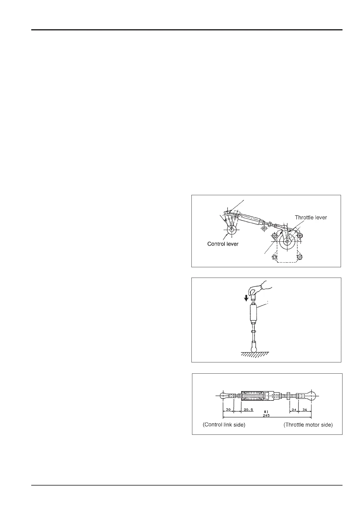
4. Removal of Throttle Link
Remove the nuts of the throttle link at the control lever A,
then remove the nuts on the opposite end of the throttle
link at the throttle lever end B. Then remove the link
without disassembly.
5. Checking operation of Throttle Link
a. Confirm whether the Spring chamber C of the link
operates normally before installing the throttle motor.
b. Stand the link and press on it from the top, and
confirm that the spring has compressed
(approx 20 mm).
c. If using the throttle link when the spring does not
compress because of its internal corrosion, the motor
will be damaged.
d. If the spring does not compress, replace it.
6. Disassembly of throttle link
a. While it is possible to disassemble the link it is
advisable to replace the unit with a new one.
b. If it is disassembled, reassemble the unit to the
dimensions shown opposite.
Note: The overall dimensions shown are not fixed as each
installation may vary.
Section C
Electrics
9803/6400
Section C
6 -1
Issue 1
Throttle Motor
A
B
C

 Loading...


