34 - 1
Section E
Hydraulics
9803/6400
Section E
34 - 1
Issue 1
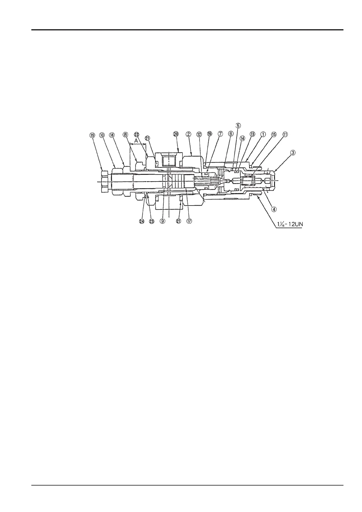
Relief Valve JS200/JS240
Dismantling
Loosen the cap 1 (Hexagonal 31.5 A/F) and remove from plug 2. Remove the sleeve 3 and take out the main poppet 4 and
spring 11.
Loosen hexagonal nut 10 (Hexagonal 22 A/F) and remove plug 19 (Hexagonal 19 A/F), piston 17, pilot poppet 6 and spring 12.
Loosen the nut 8 (Hexagonal 32 A/F) and remove the plug 18 (Hexagonal 26 A/F). Loosen the plug (Hexagonal 41 A/F) and
remove the spacer 20.
The pilot seat 5 is firmly installed at the plug 2 end so do not disassemble it.
Cleaning, Inspection
Clean all the parts with clean oil and dry with compressed air. Inspect each part.
1. Check that the seat face of each poppet and sleeve end has no defects and even surface.
2. Check that the main poppet 3, sleeve 2, piston 19 and plug 17 slide smoothly.
3. Check that the springs have no defects, deformation or wear.
4. Check that there is no foreign matter clogging the main poppet, pilot seat orifice.
5. Check that the 'O'-ring and backup ring are not worn or deformed.
If a slight defect is found during the above inspection, remove by lapping.
If an abnormal part is found, replace the relief valve assembly.
Assembly
Insert the main poppet 4 and spring 11 inside the sleeve 3 and secure with the pilot seat 5 which has 'O'-ring 13 and backup
ring 14 assembled to it. (Be careful of the assembly position of 13, 14).
Assemble the spacer 20 with the attached 'O'-ring 21 and the plug 2. (Tightening torque 78~88 N•m (57.84-65.07 lb/ft)
[Lubricated state]).
Assemble the nut 8, 'O'-ring 7 and 'O'-ring 23 and backup ring 24 to the plug 18. Screw in plug 18 to plug 22 and insert pilot
poppet 6, spring 12, piston 17. Fit 'O'-ring 9 and hexagonal nut 10 to plug 19 and temporarily assemble it.
Attach 'O'-ring 15 to plug 2 and tighten cap 1 with ring 15 installed to the valve housing (tightening torque 78~88 Nm (57.84-
65.07 lb/ft). Adjust pressure, see "Main Relief Valve Pressure".
Do not reuse 'O'-rings or backup rings. Replace with new ones.