35 - 2
Section E
Hydraulics
9803/6400
Section E
35 - 2
Issue 1
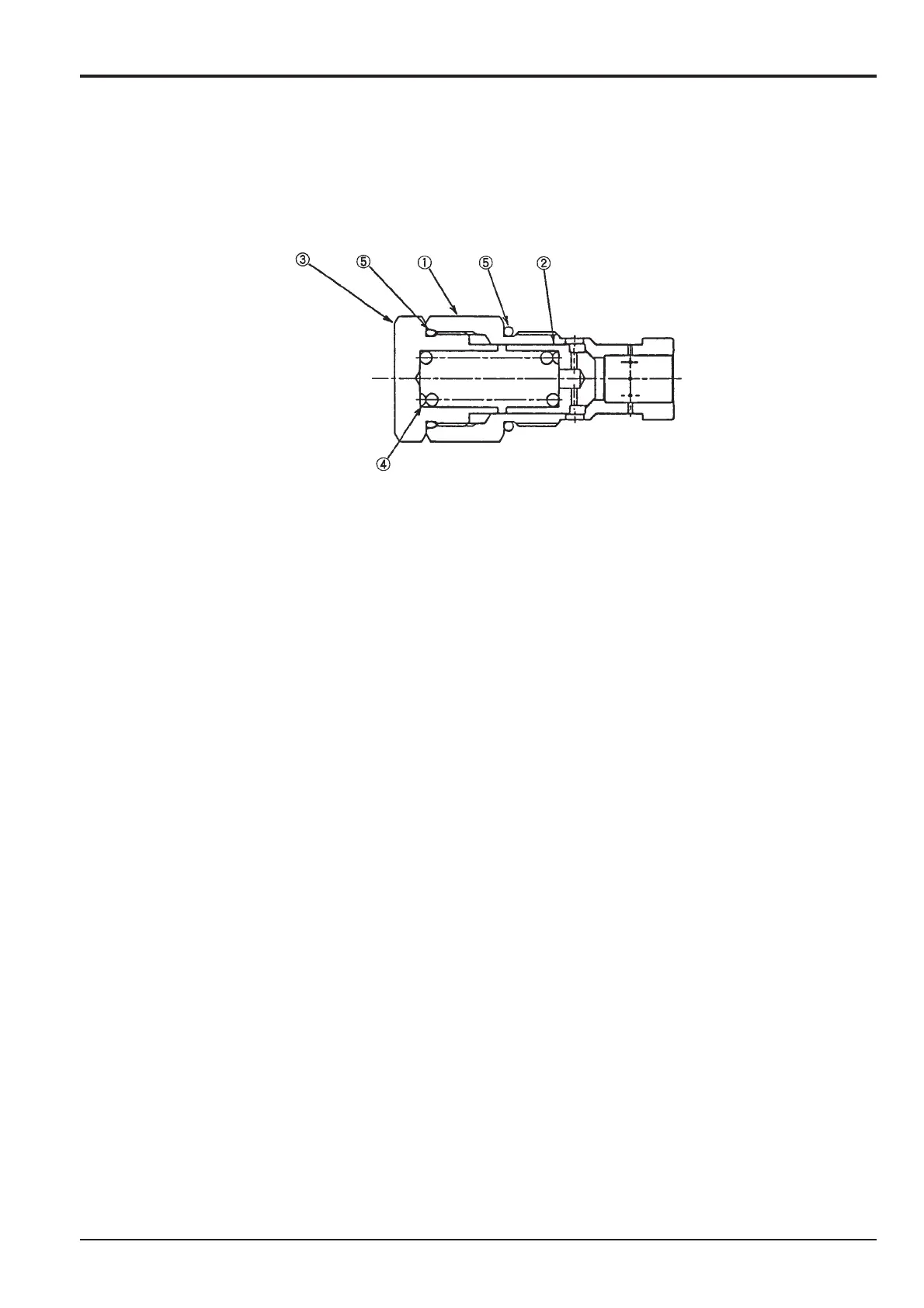
Negative Control Relief Valve JS200/JS240
Dismantling
Remove plug 3 (Hexagonal 36 A/F) and remove spring 4 and poppet 2 from the plug 1 (Hexagonal 36 A/F). Keep the
disassembled negative control relief parts in such a way that they can be assembled so as to achieve the same set relief
pressure after reassembly.
Cleaning, Inspection
Clean all the parts with clean oil and dry with compressed air. Inspect each part.
1. Check that the poppet seat surface has no defects and that the contact surface is even.
2. Check that the poppet slides smoothly.
3. Check that the springs are not broken, deformed or worn.
4. Check that the 'O'-rings are not worn or deformed.
If a slight defect is found during the above inspection, remove it by lapping.
If an abnormal part is found, replace the relief valve assembly.
Assembly
Assemble the poppet 2 and spring 4 into the plug 1. Install the 'O'-ring 5 to the plug 3 and tighten at the plug 1. Torque 88~98
Nm (65.07-72.3 lb/ft).
Install the 'O'-ring 5 to the plug 1 and assemble to the valve housing.(Torque 88~98 Nm (65.07-72.3 lb/ft)
Do not reuse the 'O'-rings and backup rings but replace with new ones.

 Loading...


