93 - 2
Relief Valves
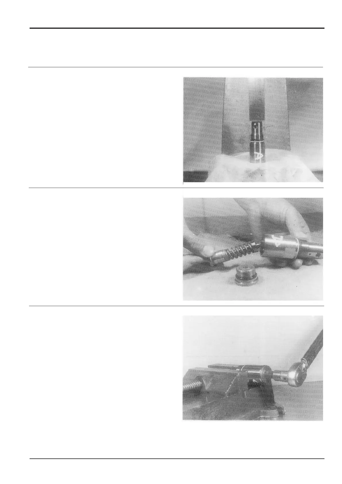
Assembly
1 Press fit seat 44 into sleeve 39 which has an 'O'-ring 41.
2 Mount poppet 43, spring 42, shim 40, piston 38, liner 51
onto sleeve 39.
3 Screw cap 37 (with a 14 mm A/F hexagonal socket) with
'O'-ring 36 and back-up 35 mounted, on to sleeve 39
and tighten to a torque of 157 Nm (116 lbf ft).
Check the relief set pressure.
The correlation between the set pressure of the relief
valve and the adjusting shims is shown below.
However, adjustment must not be attempted if the
pressure cannot be checked.
A 0.1 mm (0.003 in) shim equals 5 kgf/cm
2
(71 lbf/in
2
)
approximately.
Section E
Hydraulics
9803/6400
Section E
93 - 2
Issue 2*
Slew Motor
*