10 - 5
Assembly (continued)
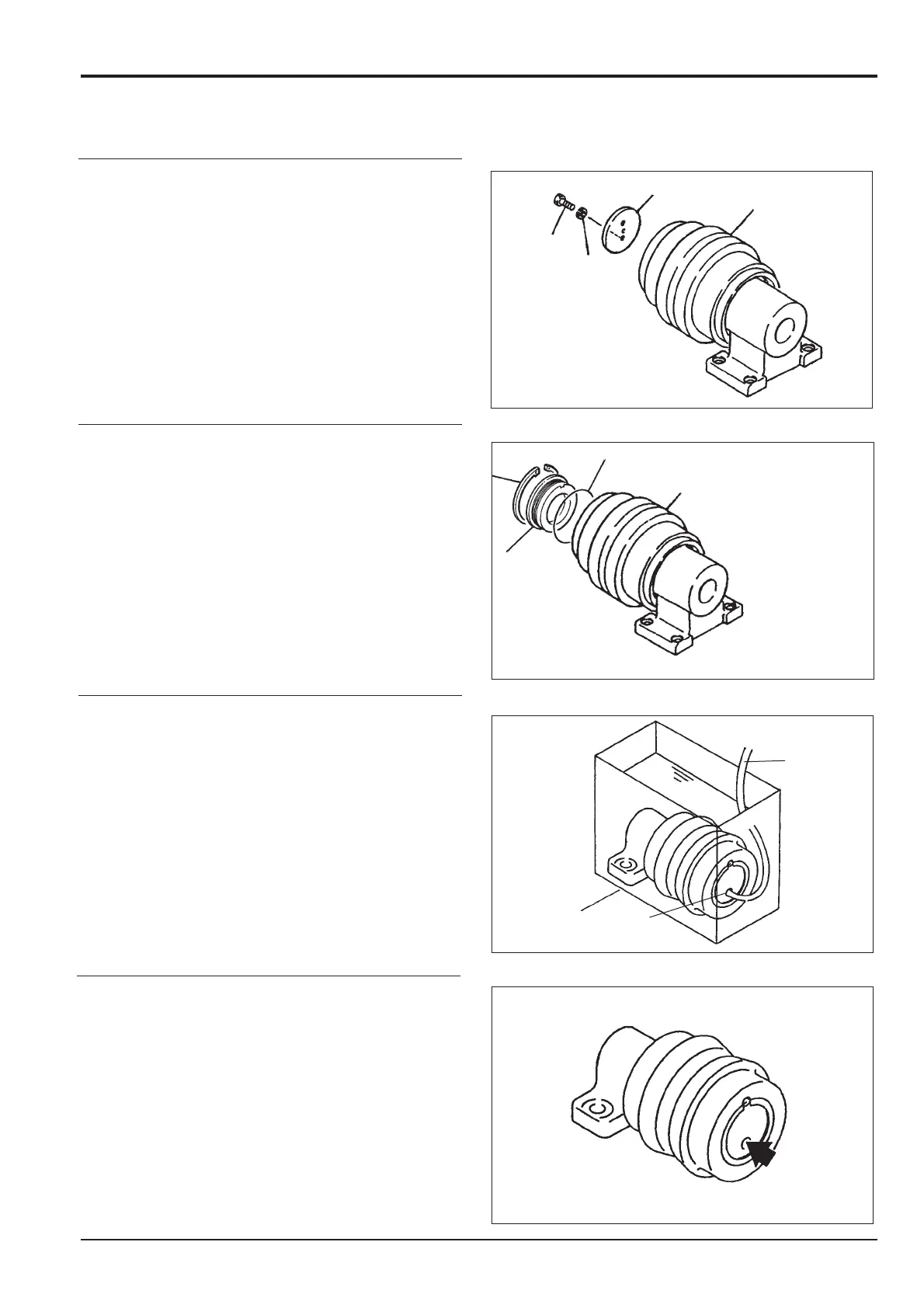
6. Apply grease to the inside face of the thrust plate Q and
install it on the shaft using bolt R and washer S.
7. Apply grease to a new 'O'-ring T and install it onto cover
D. Install the cover D to the roller A. Retain with the
retaining ring C.
8. Using extreme care to prevent water entering the
assembly, lower it into a tank of water. Connect a
compressed air pipe V to the port N, check for air
bubbles.
Apply a pressure of 1.9 bar (28 lb/in
2
).
9. Remove the assembly from the tank.
Dry with compressed air. Add the specified oil (see
Routine Maintenance).
Install plug B using an appropriate pipe thread sealant.
Section J
Track and Running Gear
9803/6400
Section J
10 - 5
Issue 1
Top Roller (continued)
R
S
Q
A
A
T
D
C
W
V
B

 Loading...


