8 - 40
Setting-up Procedures
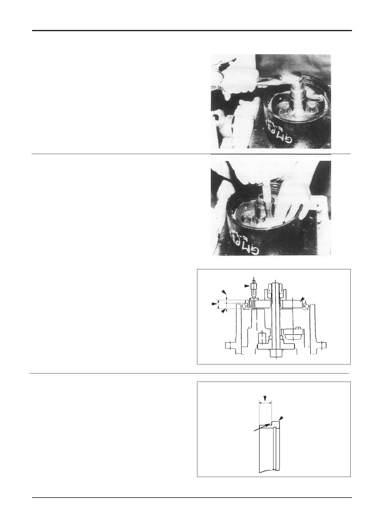
Pre-load of Bearings 21
1 Install the main bearing pre-load adjusting jig (see
Service Tools, Section 1) into the spindle 2, making sure
the jig seats evenly with bearing 21 and does not foul
taper bearing 22. Tighten the jig nut to a torque of 39.2
Nm (28.9 lbf ft).
2 Measure depth A via the measurement hole in jig E
using a depth micrometer F. If not already known,
measure the thickness B of the lip of jig E.
Calculated dimension C (i.e. A - B) determines the
required dimension D of holding flange (see step 3).
3 Measure dimension D on the existing holding flange 3.
Proceed according to the following guidelines:
a If dimension D is less than the calculated dimension
C, grind surface G to achieve the required measurement
before assembling.
b If dimension D is within the tolerance of the
calculated dimension C, use the holding flange as it is.
c If dimension D is greater than the calculated
dimension C replace both the holding flange 3 and the
spindle 2. Having reached the appropriate point of the
assembly procedure, re-check the bearings pre-load as
described above.
Section F Transmission
9803/6020
Section F
8 - 40
Issue 1
Track Gearbox
2879840
287950
DD
33
GG
EE
FF
AA
CC
BB
 Loading...


