10 - 5
Assembly (cont’d)
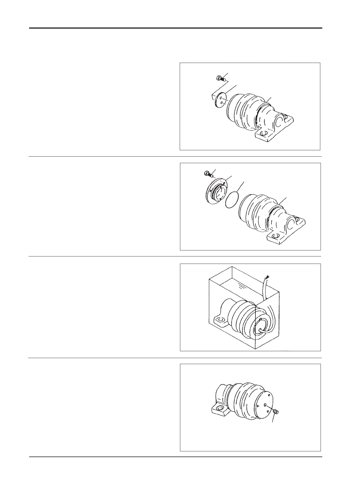
6 Apply grease to the inside face of thrust plate F and
install it on the shaft using bolts E Torque tighten to 62 -
73 Nm (46 - 54 lbf ft.).
7 Apply grease to a new 'O'-ring D and install it onto
cover C. Install the cover C to the roller A. Retain with
bolts.Torque tighten the bolts to 27 - 31 Nm (20 - 23 lbf
ft.).
8 Remove plug B and connect compressed air pipe V to
the port. Using extreme care to prevent water entering
the assembly, lower it into a tank of water.
Apply air pressure of 1.9 bar (28 lbf/in
2
) and check that
there are no bubbles leaking from the unit. If leakage
occurs dismantle and re-assemble, taking extra care
when fitting new seals.
9 Remove the assembly from the tank. Dry with
compressed air. Fill with oil (see Fluids and Lubricants,
Section 3) and install plug B using an appropriate pipe
thread sealant.
Section J Track and Running Gear
9803/6020
Section J
10 - 5
Issue 1
Top Roller
B
286690
286680
286750
286770
A
E
C
D
A
F
E
VV
 Loading...


