Part No. 960-000193R_Rev. A © 2017 JCM American Corporation
GEN5™ Printer JCM® Training Overview September, 2017
COMPONENT LOCATIONS
C
OMPONENT
N
AMES
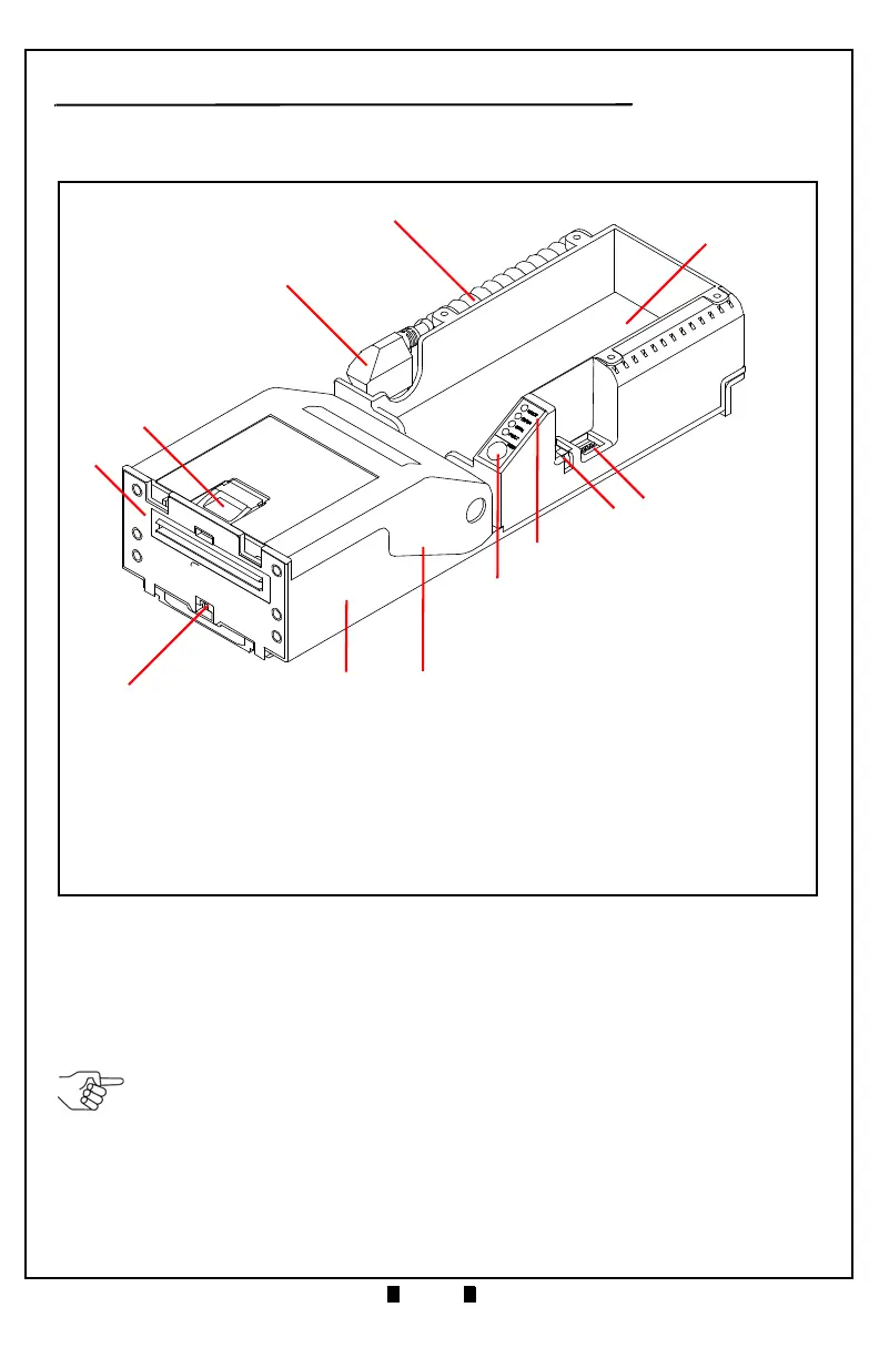
Figure 2 illustrates the GEN5 Component Names and Locations.
DIP S
WITCH
S
ETTINGS
The GEN5 Printer includes six (6) DIP Switches, located under the rubber boot
(Figure 2 j) adjacent to the USB Update Port (Figure 2 k). The DIP Switches
are used to set operational parameters, and vary by manufacturer.
Figure 2 GEN5 Printer Component Names
a) RS232/USB Coil Interface Cable
b) Coil Interface Cable Connector
c) Lid Latch
d) Copper Shield
e) Bezel LED Connector
f) Bottom Tray
g) Upper Lid
h) Feed Button
i) Status LEDs
j) Rubber Boot
k) USB Update Port
l) Paper Tray (300 Ticket)
NOTE: To verify the correct DIP Switch settings for the GEN5 Printer Unit, refer to the
Software Information Sheet for the Manufacturer and installed Firmware version.