6 USER MANUAL
Mil-Aero connectors are ber optic connectors used
in aerospace applications. Established by the Airlines
Electronic Engineering Committee (AEEC), ARINC 801
is part of the ARINC 800 series of ber optic standards
for avionics networking. All ARINC 801 connectors
utilize a 1.25 mm ferrule and are mated in a pin and
socket conguration. While all of the ARINC 801
connectors utilize a “plug and receptacle” design,
there are dierent design types within the standard.
MILAERO CONNECTORS
Receptacle
Alignment Guide
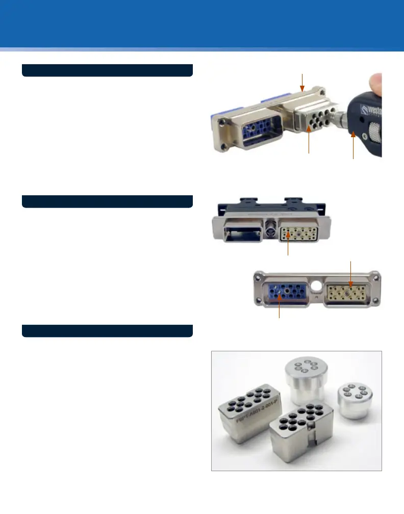
Plug: The male interface of an ARINC
801 connection.
Receptacle: The female interface of an ARINC
801 connection.
Pin: The exposed 1.25 mm ferrule.
Socket: The unexposed ferrule inside the
alignment sleeve.
KEY TERMS
Plug
Socket
Receptacle
Pin
Socket
ARINC 801
FBP Probe
Microscope
JDSU oers a series of alignment guides that t the
shell sizes of the respective plug and receptacle of
various ARINC 801 connectors. These guides provide a
compatible interface for the inspection and cleaning
of pins or sockets specic to each type of connector.
With the JDSU FBP probe microscope and handheld
video display, JDSU's ARINC 801 alignment guides
provide the means for a quick and easy inspection
of these rugged, multi-termini connectors, in a eld
or factory environment. In addition, these guides can
also be used with the JDSU CleanBlast™ system to
clean away debris and dirt from the optical end-faces
of ARINC 801 connectivity.
JDSU ALIGNMENT GUIDES
 Loading...