TABLE
INSERT
The
table
insert
(A)
is
placed
in
the opening in the
saw
table,
as shown in
Fig.
22,
and
should
be
leve!
with
the
surface
of
the saw
table.
To
adjust
the
table
insert
use
~
straight
edge and
screwdriver
and
turn
the
four
adjusting
screws
in
or out
until
the
insert
is
flush
with
the
table,
as shown
in
Fig.
22.
CONNECTING
SAW
TO
POWER
SOURCE
A separate electrical
circuit
should
be
used
for
your
power tools. This
circuit
should
not
be less
than
#12
wire and should be
protected
with a
20
Amp
ti
me
lag
fuse.
If
an exten·
Sion
cor,d
is
used,
use
on!y
3-wire extension cards which have 3-prong grounding
type
plugs and-_.3-pole receptacles which
accept
the
tools
plug. For distances up_to
100
feet use
#12
wire
..
For
distances
up
to
150
feet use
#10
wire. Before connecting
the
motor
ta
the
power line,.make sure
the
switch
is
in
the
"OFF"
position and be sure
that
the
electric
current
is
of
the
same
characteristics
as
stamped on
motor
nameplate. Al! li
ne
connec-
tions
should make.good contact. Running on
law
voltage
will
injure the mo tor.
GROUNDED
OUTLET
BOX-:1
. CURRENT
"
CAR~YING
~
PRONGS
~
•
~
GROUNDING
BLADE"'
s
IS
l.ONGEST
OF
THE 3 BLADES
Fig.
23
Fig. 24
10
liS
VOLT,
SINGLE
l'HASE
OPERATION
This
tool
must be grounded
while
in
use
to
protect
the
operator
from
electric
shock.
The
motors recom-
mended
for
use
with
your
saw
are
shipped
_wir.ed
for
115
Volt,
Single
Phase, and are equipped
with
an
ap·
proved
3-conductor
cord and 3·prong grounding
type
plug
to
fit
the proper grounding
type
receptacle,
as
shown
in
Fig.
23.
The
green
conductor
in
the cord
is the grounding
wire.
Never
connect-
the
gre-en
wire
to
a 1
ive
terminal.
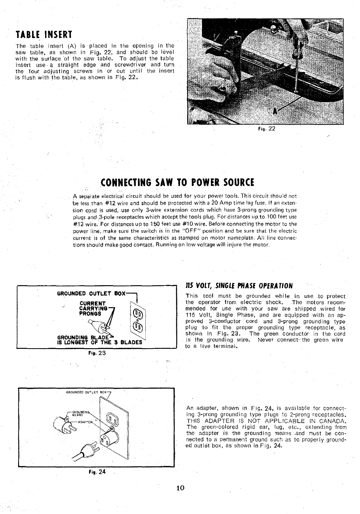
An adapter, shawn in
Fig.
24,
is avai lab·!e for
connect-
ing 3-prong grounding type plugs
to
2-prong
receptacles.
THIS
ADAPTER
IS
NOT
APPLICABLE
IN
CANADA.
The
green·colored
rigid
ear, lug,
etc.,
extending
from
the adapter
is
the grounding means .and must be
con-
nected
to
a permanent ground
such
as
to
properly
ground·
ed out
let
box, as shown
in
Fig.
24.