RIP
FENCE
OPERATION
AND
ADJUSTMENTS
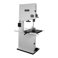
The
ri·p
fence can
be
used
on
eitlier side
of
the saw
blade. The most
common
location
is
on
the right hand
side. The
rip
tence is guided by means of guide
rails
fastened to the front '\nd rear
of
the table. The front
guide rai
1
is
calibrated ta show the distance the tence
is set from the .saw blade.
Ta
"move
the
rip
tence, rai
se
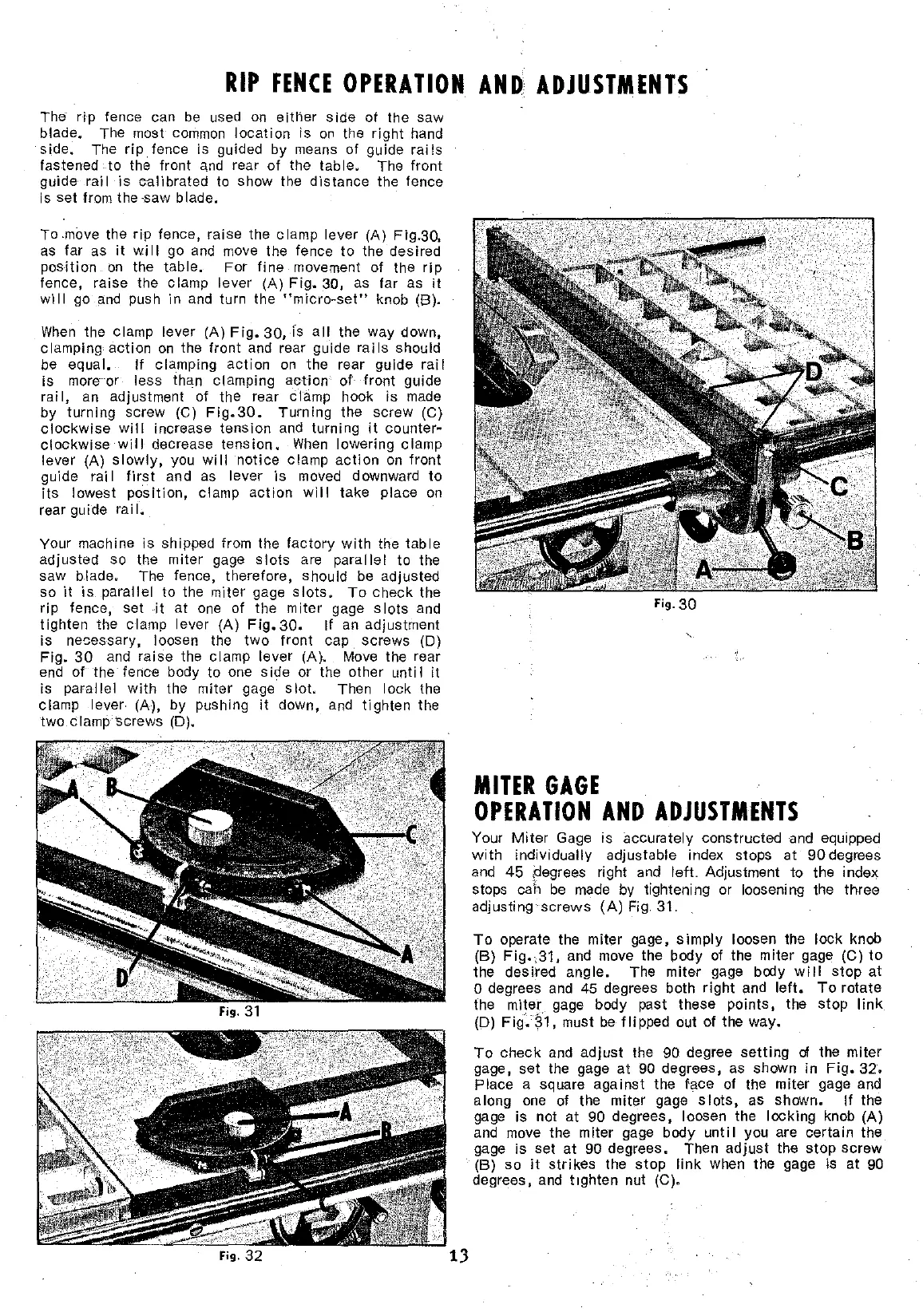
the clamp lever (A) Fig.30,
as
far as
it
wi Il go
and
move
the tence
ta
the desired
position
on
the table. For fine movement of the
rip
tence, raise the clamp lever (A)
Fig.
30, as far as
il
will
go
and
push in
and
turn the
"micro-set"
knob (B).
When
the clamp lever (A)
Fig.
30,
fs
ali
the way dawn,
clamping action
on
the front
and
rear guide
rails
should
be
equal. If clamping action
on
the rear guide
rail
is more or less !han clamping
action
of
front guide
rai
1,
an adjustment
of
the rear Clàmp hook is made
by turnlng screw (C)
Fig.30.
Turning the screw (C)
clockwise will increase tension
and
turning
it
counter~
clockwise
will
decrease tension.
When
lowering clamp
lever (A)
slowly,
you
will
notice clamp
action
on
front
guide rai
1
first
and as lever
is
moved downward
ta
its
lowest position, clamp
action
will
take place
on
rear guide rai
1.
Yaur machine
is
shipped from the factory
with
the
table
adjusted so the miter gage
slots
are
parallel
to the
saw blade. The tence, therefore, should
be
adjusted
sa
it
is
parai lei
ta
the miter gage
slots.
To
check the
rip
tence, set
it
at
one
of the miter gage
slots
and
tighten the clamp lever (A)
Fig.
30.
If
an
adjustment
is nesessary, loosen the
two
front
cap.
screws (D)
Fig.
30
and
raise the clamp lever (A).
Move
the rear
end
of the· tence body ta one s ide or the other
un
ti 1
it
is parallel
with
the miter gage
slot.
Then lock the
clamp lever (A), by pushing
il
dawn,
and
tighten the
two
clamp screws (D).
MITER
GAGE
OPERATION
AND
ADJUSTMENTS
Your
Miter
Gage
is
accurately constructed
and
equipped
with
individually adjustable index stops at
90
degrees
and
45
t]egrees righi
and
lefL
Adjustment ta the index
stops cah
be
made
by
tightening or loosening the three
adj
us
ting
screws
(A)
Fig"
31"
Ta
operate the miter gage,
simply
loosen the lock knob
(B)
Fig.,31.
and move the body of the miter gage (C)
ta
the desired angle. The miter gage body
will
stop
at
o degrees
and
45
degrees bath
right
and
left.
Ta
rotate
the miter gage body past these points, the stop
link
(D)
Fig.~1,
must
be
flipped
out of the way.
Ta
check
and
adjust
the 90 degree
setting
d the miter
gage, set the gage
at
90
degrees, as shawn in
Fig.
32.
Place a square
against
the
lace
of the miter gage
and
along
one
of the miter gage
slots,
as shawn.
If
the
gage is not at 90 degrees, loosen the locking knob (A)
and
move the miter gage body
until
you are certain the
gage is set at
90 degrees. Then
adjust
the
stop
screw
(B) sa
it
strikes
the
stop
link
when the gage is at
90
degrees, and t1ghten nul (C).