10
7.0 Operating controls
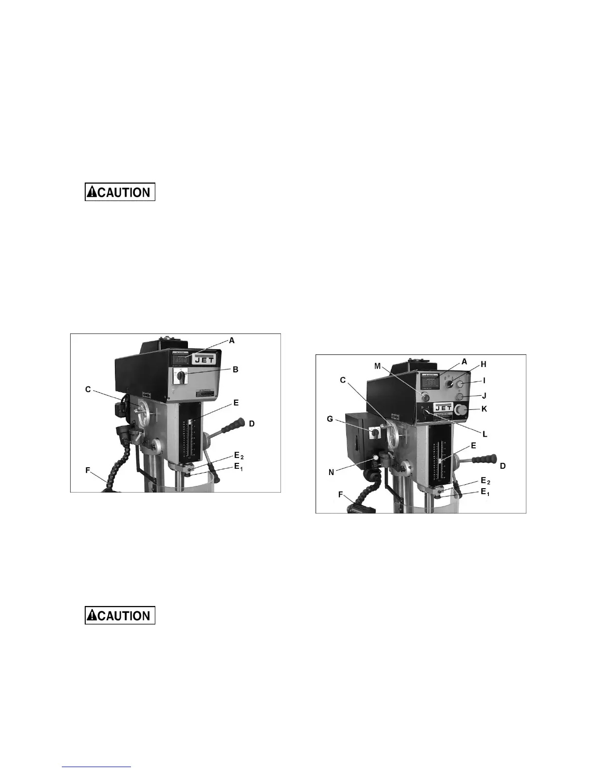
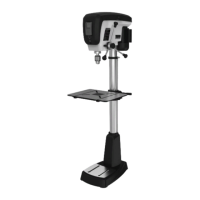
7.1 JDP-20VS-1/3 controls
Refer to Figure 7-1.
LED Display (A): Shows spindle RPM selected by
speed control handwheel.
On/Fwd/Rev switch (B): Turns on spindle and
selects rotation direction.
Speed control handwheel (C): Turn counter-
clockwise to increase spindle speed.
Move handwheel only while
spindle is rotating. Failure to comply may
cause damage to speed mechanism.
Downfeed handle (D): Raises and lowers quill.
Depth stop (E): Can be set for depths up to 6-
inches.
Adjustment knob (E
1
): Sets depth stop position.
Lock knob (E
2
): Locks setting of depth stop.
Work light (F): Has separate on/off switch atop
shade; flexible positioning.
Figure 7-1: JDP-20VS-1/3 controls
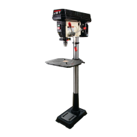
7.2 JDP-20VST controls
Refer to Figure 7-2.
LED Display (A): Shows spindle RPM selected by
speed control handwheel.
Speed control handwheel (C): Turn counter-
clockwise to increase spindle speed.
Move handwheel only while
spindle is rotating. Failure to comply may
cause damage to speed mechanism.
Downfeed handle (D): Raises and lowers quill.
Depth stop (E): Can be set for depths up to 6-
inches. Activates limit switches in tapping mode.
Adjustment knob (E
1
): Sets depth stop position.
Lock knob (E
2
): Locks setting of depth stop.
Work light (F): Has separate on/off switch atop
shade; flexible positioning.
Speed range switch (G): Two ranges. Middle
position is neutral – spindle off. Must be set to high
or low before front panel controls will function.
Drill mode switch (H): Selects drill or tap mode.
Middle position is neutral – spindle will not move.
Spindle on button (I): Starts spindle rotation.
Spindle off button (J): Stops spindle rotation.
(Other functions such as coolant pump will continue
to operate.)
E-Stop (K): Emergency stop button shuts down all
drill press functions. To restart drill press, turn E-
stop button clockwise until it disengages.
Coolant pump switch (L): (Optional accessory);
starts and stops coolant pump circulation.
Reverse spindle (M): If tapping is interrupted,
press and hold this button to reverse tap from
workpiece. When button is released, spindle will
resume forward rotation.
Power on light (N): Indicates electrical current is
flowing to machine.
Figure 7-2: JDP-20VST controls
8.0 Adjustments
8.1 Depth stop
The drilling depth indicator (E, Figures 7-1 and 7-2)
can be set for depths up to 6 inches (152.4 mm).
8.1.1 For drilling (all models)
1. (Set switch to drill mode (H) on JDP-20VST.)
2. Before starting motor, use downfeed handle to
set end of drill against surface into which hole is
to be drilled.