Figure 6-7
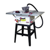
6.8 Rails and fence
To install front and rear rails and fence, consult
manual M-725005 which accompanies your fence
assembly, then proceed to sect. 5.11.
6.9 Wood extension table
To install the optional wood table, consult manual
M-725005, which accompanies your fence
assembly, then proceed to sect. 5.11.
6.10 Switch bracket
See Figure 5-8.
Use two screws with washers (HP-11) to secure
switch bracket to front rail.
Figure 5-8
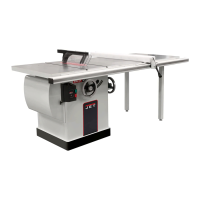
6.11 Dust collection
Use of a dust collection system (not provided) is
strongly recommended during table saw operation.
It will help keep the shop clean, as well as prevent
potential health issues due to dust inhalation.
A dust collection system, with minimum capacity of
400 CFM (cubic feet per minute) should be
connected to the port via a 4-inch (101.6mm)
diameter hose (not included) and secured with a
hose clamp. Note: Dryer vent hose is not
acceptable for this purpose.
An extensive line of JET dust collectors is available;
contact your dealer or visit our website for
information.
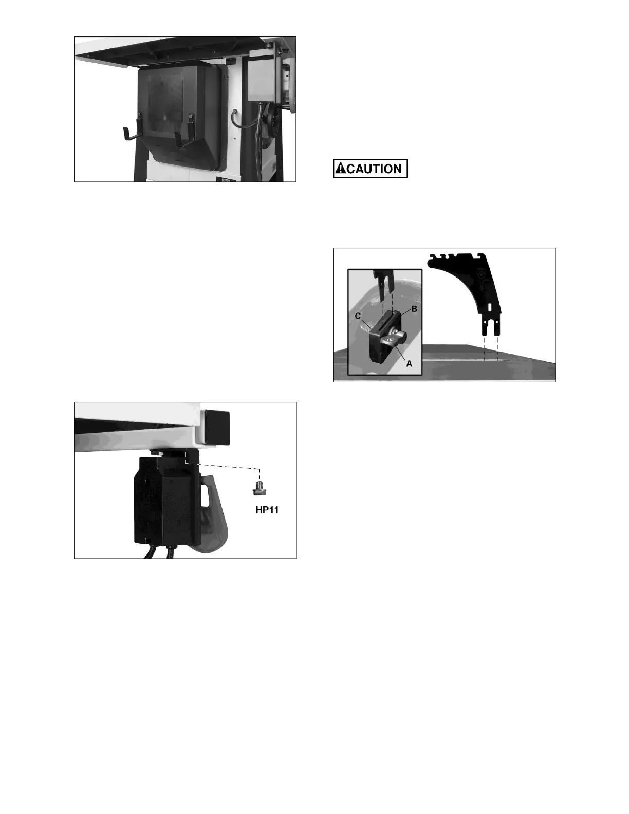
6.12 Riving knife
See Figure 5-9.
1. Disconnect machine from power source.
2. Set saw blade to 90° (vertical) position and
raise it all the way (refer to sect. 7.1).
3. Remove table insert by rotating locking knob
(shown at M, Figure 5-14) and lift up insert
using finger hole.
Use care when working around
an installed blade.
4. Through the saw table opening, pull up lever
(A, Figure 5-9). The floating clamp block (B)
will move away from the fixed block (C),
leaving a gap.
Figure 5-9
5. Slide tabs of riving knife (D) into slot between
the two blocks, all the way down onto
mounting stud.
6. Push down lever (A) to secure riving knife.
The clamping block (Figure 5-9) is adjusted at the
factory and no further adjustment of blade guard
and riving knife assembly should be necessary.
However, proper alignment is very important.
Before operating table saw, read sect. 7.3, Riving
knife alignment, to verify and follow the adjustment
procedure if necessary.
6.13 Anti-kickback pawls
See Figures 5-10 and 5-11.
1. Push and hold button (D) on opposite side of
the head to release the catch pin. Mount pawl
assembly straight down, in the location shown
in Figure 10.
2. Pivot head and push it downward (Figure 5-11)
until there is an audible click. Make sure you
hear the click to verify that pawl assembly is
secure.
 Loading...