SECTION 3 - CHASSIS & TURNTABLE
3121201 – JLG Lift – 3-33
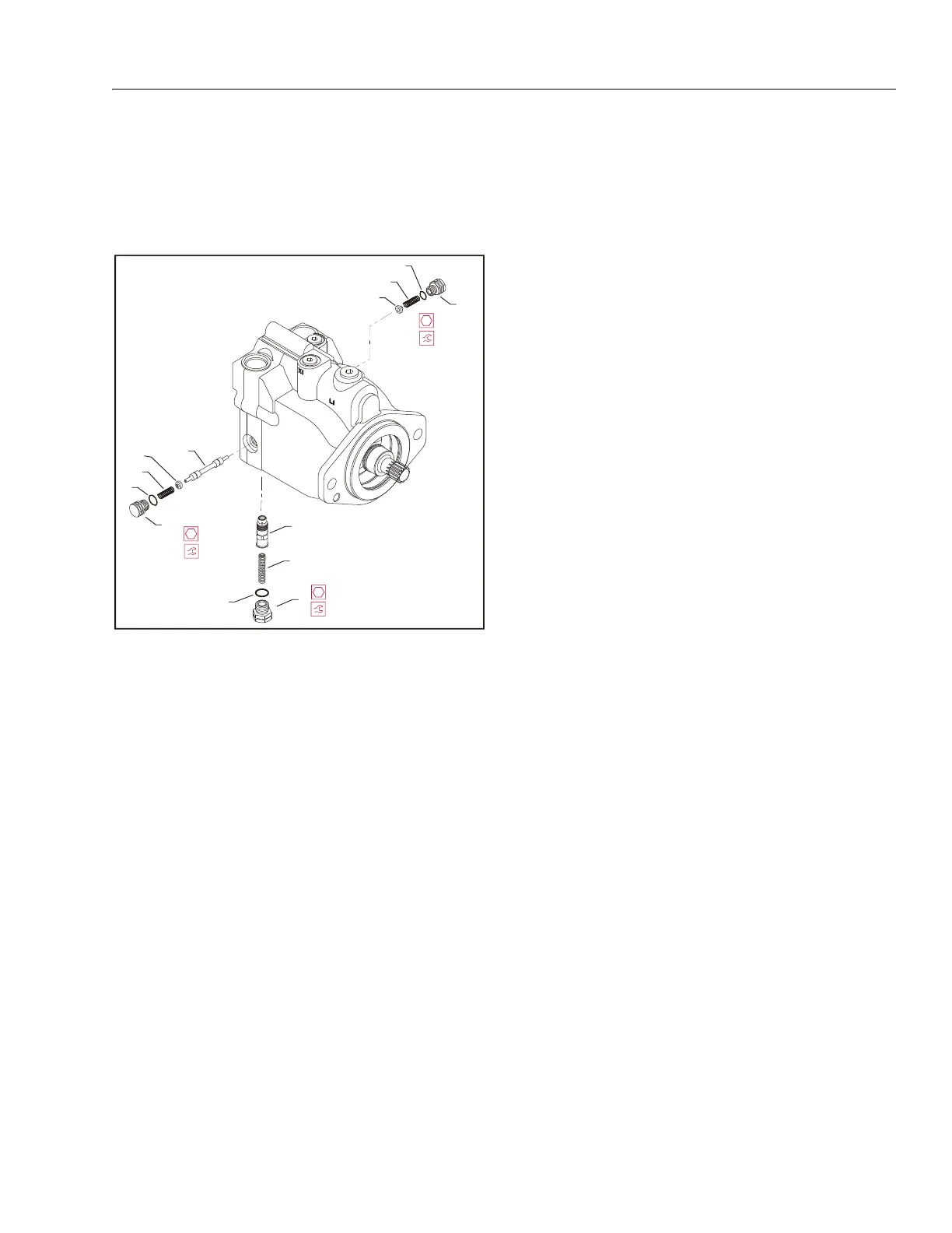
Loop Flushing Valve
REMOVAL
1. Using a 11/16 in internal hex wrench remove plug
(1) and (2).
2. Using a 1/4 in hex wrench remove plug (3).
3. Remove O-rings (4, 5, and 6).
4. Using pliers, remove centering springs (7, 8, and 9).
5. Remove spring retaining washers (10 and 11).
6. Remove shift spool (12).
7. Remove orifice poppet (13).
INSPECT THE COMPONENTS
Inspect new O-rings and the sealing area for rust, wear, or
contamination. Also check springs and poppet for wear.
INSTALLATION
1. Install orifice poppet (13).
2. Install shift spool (12).
3. Install spring retaining washers onto springs (10 and
11).
4. Carefully install centering springs (7, 8, and 9).
5. Install new O-rings (6, 4, and 5).
6. Using a 1/4 in hex wrench torque plug (3) to 20 ft.
lbs. (27 Nm).
7. Using a 11/16 in internal hex, torque plugs (2 and 1)
to 27 ft.lbs. (37 Nm).
2
6
9
11
1
4
8
10
12
5
3
7
13
(37 Nm)
27 ft.lbs.
11/16 in
(37 Nm)
27 ft.lbs.
11/16 in
(27 Nm)
20 ft.lbs.
5/8 in
1. Plug
2. Plug
3. Plug
4. O-ring
5. O-ring
6. O-ring
7. Spring
8. Spring
9. Spring
10. Washer
11. Washer
12. Shift Spool
13. Orifice Poppet
Figure 3-20. Loop Flushing Spool