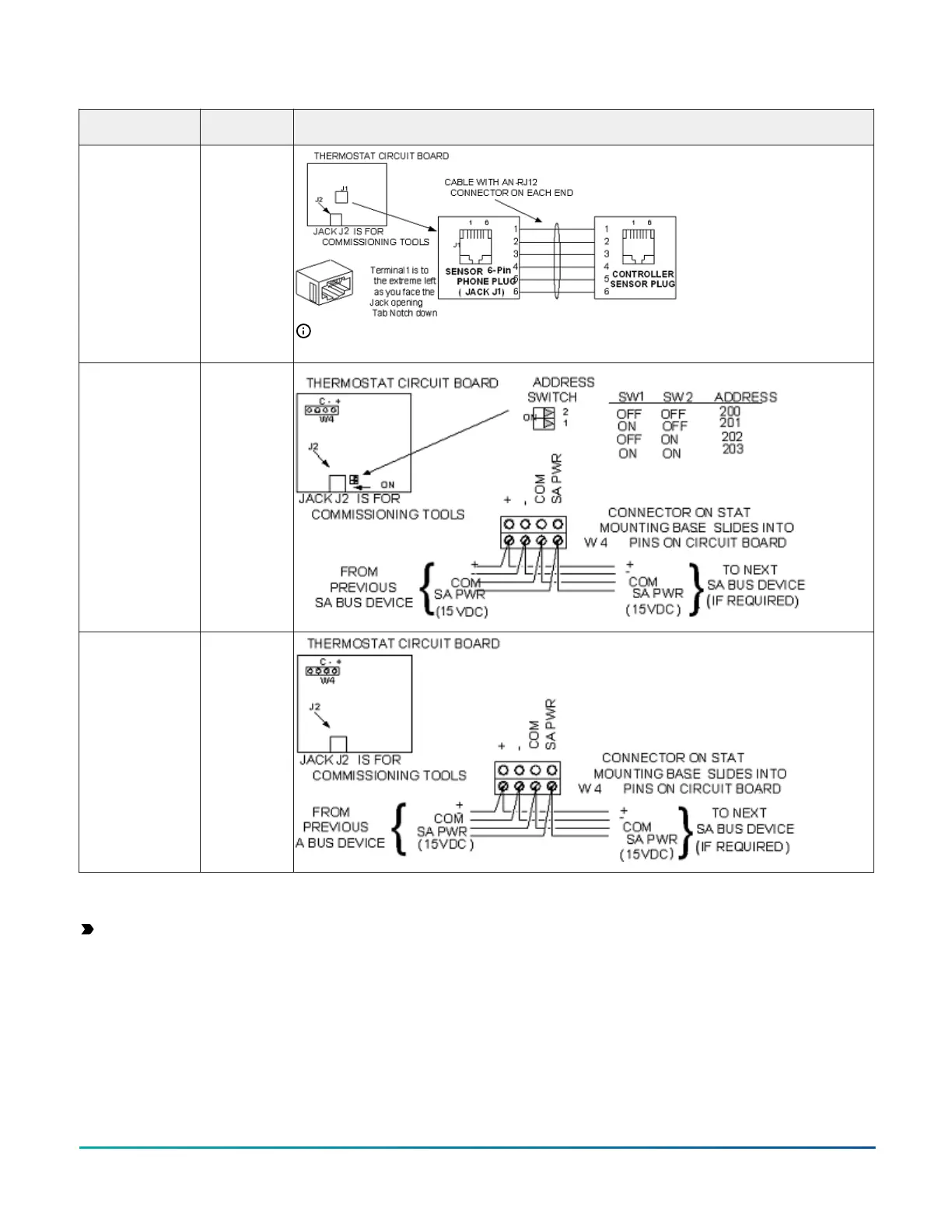
Table 6: Termination details
Type of field
device
Type of Input/
Output
Termination diagrams
Network Stat with
Phone Jack (Fixed
Address = 199)
SA Bus
Note: The bottom jack (J2) on the TE-700 and TE-6x00 Series Sensors is not usable as a zone
bus or an SAB connection.
Network Stat
with Terminals
Addressable
SA Bus
Network Stat with
Terminals (Fixed
Address = 199)
SA Bus
Setup and adjustments
Important: Electrostatic discharge can damage
controller components. Use proper electrostatic
discharge precautions during installation, setup, and
servicing to avoid damaging the controller.
Configuring N2 communications
About this task:
N2-capable controllers support the full range of possible
N2 device addresses provided by the N2 protocol standard
(1-254).
To configure a controller to communicate using the N2
protocol, complete the following steps:
1. Disconnect the 24 VAC supply from the controller.
2. Set the address switches to the desired N2 address.
For details about setting a device address, see
Setting the device address.
3. Reconnect the 24 VAC supply to the controller.
4. Using an SA bus connection, download the
firmware and controller application file configured
for N2 to the controller.
M4-CGM General Purpose Application Controller Installation Guide 15