Note: Do not use the modular SA Bus port and the
terminal block SA Bus simultaneously. Only use one
of these connections at a time.
Note: The CGM controller is the EOL for the SA Bus.
FC bus port
The FC bus port on the front of the controller is an RJ-12,
6-position modular jack that provides a connection for the
Mobile Access Portal (MAP) Gateway, or the ZFR/ZFR Pro
Wireless Field Bus Router.
The FC bus port is connected internally to the FC bus
terminal block. See Table 5 for more information
about communication bus port functions, ratings, and
requirements. The FC bus port pin assignment is shown in
Figure 7.
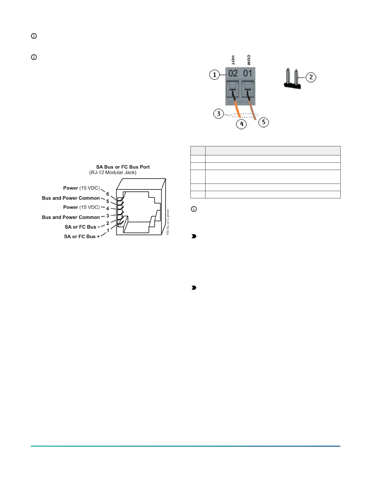
Figure 7: Pin number assignments for FC bus and SA
bus ports on equipment controllers
SA Bus port
The SA Bus port on the front of the controller is an RJ-12,
6-position modular jack that provides a connection for the
MAP Gateway, the VAV Balancing Tool, the DIS1710 local
controller display, specified network sensors, or other SA
Bus devices with RJ-12 plugs. When the CGM is configured
for N2 network communication, you must download and
commission the controller using the SA Bus port.
The Sensor port is connected internally to the SA
bus terminal block. See Table 5 for more information
about communication bus port functions, ratings, and
requirements. The SA Bus port pin assignment is shown in
Figure 7.
Supply power terminal block
The 24 VAC supply power terminal block is a gray,
removable, 2-pin terminal block that fits into a board-
mounted pin header on the top right of the controller.
Wire the 24 VAC supply power wires from the transformer
to the HOT and COM terminals on the terminal plug as
shown in Figure 8. For more information about the Supply
Power Terminal Block, see Table 5.
Figure 8: 24 VAC supply power terminal block wiring
Table 2: Supply power terminal block wiring
Description
1 Supply power terminal block
2 Supply power terminal header
3
Wires from Johnson Controls 24 VAC, class 2 power
transformer
4 24 VAC (Orange wire)
5 COM (Brown wire)
Note: The supply power wire colors may be different
on transformers from other manufacturers. Refer to
the transformer manufacturer’s instructions and the
project installation drawings for wiring details.
Important: Connect 24 VAC supply power to the
equipment controller and all other network devices
so that transformer phasing is uniform across the
network devices. Powering network devices with
uniform 24 VAC supply power phasing reduces
noise, interference, and ground loop problems. The
equipment controller does not require an earth
ground connection.
Important: Power wires must be less than 30 meters
(100 ft) between controller and transformer
Terminal wiring guidelines, functions,
ratings, and requirements
This section provides further guidelines on input and
output wiring, maximum cable length versus load current,
and SA Bus and supply power wiring.
For information about removing a terminal block from the
controller, see Removing a terminal block.
Input and Output wiring guidelines
Table 3 provides information and guidelines about the
functions, ratings, and requirements for the controller
input and output terminals, and Table 4 also references
guidelines for determining proper wire sizes and cable
lengths.
In addition to the wiring guidelines in Table 3, observe
these guidelines when wiring controller inputs and
outputs:
• Run all low-voltage wiring and cables separate from
high-voltage wiring.
M4-CGM General Purpose Application Controller Installation Guide 5