no connected Network Sensor, the startup of this default
state will be delayed by 30 seconds as the controller
attempts to establish connection with the sensor.
Commissioning equipment controllers
You commission MS/TP equipment controllers with the
CCT software using either Mobile Access Portal (MAP)
Gateway , a ZFR wireless dongle, or in passthrough
mode when connected to a Network Engine. For detailed
information about commissioning equipment controllers,
refer to Controller Tool Help (LIT-12011147).
Troubleshooting equipment
controllers
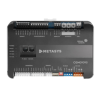
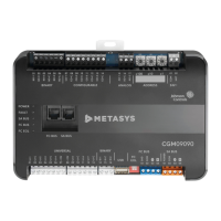
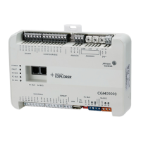
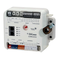
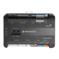
Observe the Status LEDs on the front of the equipment
controller. Table 10 provides LED status indicator
information for troubleshooting the controller. To
troubleshoot an integral or local controller display, refer
to the DIS1710 Local Controller Display Technical Bulletin
(LIT-12011666).
LED status and states
Table 10: Status LEDs and description of LED states
LED label LED color Normal LED state Description of LED states
POWER Green On Steady
Off Steady = No Supply Power or the controller’s polyswitch/resettable fuse is
open. Check Output wiring for short circuits and cycle power to controller.
On Steady = Power Connected
FAULT Red Off Steady
2 blinks followed by long pause = Controller powered on in default state. For more
information about this default state, see Input/Output Wiring Validation.
Off Steady = No Faults
On Steady = Device Fault; no application loaded; Main Code download required, if
controller is in Boot mode, or a firmware mismatch exists between the CGM and
the ZFR1811 Wireless Field Bus Router.
Blink - 2 Hz = Startup in progress, not ready for normal operation
Rapid blink = SA Bus communications issue
SA BUS Green Blink - 2 Hz
Blink - 2 Hz = Data Transmission (normal communication)
Off Steady = No Data Transmission (N/A - auto baud not supported)
On Steady = Communication lost, waiting to join communication ring
FC BUS Green Blink - 2 Hz
Blink - 2 Hz = Data Transmission (normal communication)
Off Steady = No Data Transmission (auto baud in progress)
On Steady = Communication lost, waiting to join communication ring
EOL Amber
Off (Except on
terminating
devices)
On Steady = EOL switch in ON position
Off Steady = EOL switch in Off position
M4-CGM General Purpose Application Controller Installation Guide 19
 Loading...


