CAUTION
Risk of Property Damage:
Do not apply power to the system before checking
all wiring connections. Short circuited or improperly
connected wires may result in permanent damage to
the equipment.
ATTENTION
Mise En Garde: Risque de dégâts matériels:
Ne pas mettre le système sous tension avant
d'avoir vérifié tous les raccords de câblage. Des
fils formant un court-circuit ou connectés de façon
incorrecte risquent d'endommager irrémédiablement
l'équipement.
Important: Do not exceed the controller electrical
ratings. Exceeding controller electrical ratings can
result in permanent damage to the controller and
void any warranty.
Important: Use copper conductors only. Make
all wiring in accordance with local, national, and
regional regulations.
Important: Electrostatic discharge can damage
controller components. Use proper electrostatic
discharge precautions during installation, setup, and
servicing to avoid damaging the controller.
For detailed information about configuring and wiring
an MS/TP Bus, FC bus, and SA bus, refer to the MS/TP
Communications Bus Technical Bulletin (LIT-12011034). For
detailed information about wiring an N2 network, refer to
the N2 Communications Bus Technical Bulletin (LIT-636018).
Terminal blocks and bus ports
See Physical features for terminal block and bus port
locations on the CGM controller. Observe the following
guidelines when wiring a CGM controller.
Input and Output terminal blocks
CGM controllers have removable input and output
terminal blocks. All of the input terminal blocks are
located on the bottom of the controller, and the output
terminal blocks are located on the top of the controller.
For information about removing a terminal block, see
Removing a terminal block. For more information about
I/O terminal functions, requirements, and ratings,
see Terminal wiring guidelines, functions, ratings, and
requirements.
FC bus terminal block (or N2 protocol as
required)
The FC bus terminal block is a blue, removable, 4-pin
terminal block that fits into a board-mounted pin header.
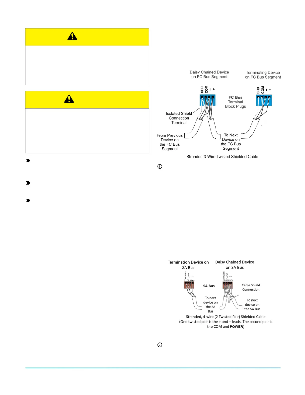
When connecting the CGM to the FC Bus, wire the bus
terminal blocks on the controller and other FC Bus devices
in a daisy-chain configuration using 3-wire twisted,
shielded cable as shown in Figure 5. For more information
about FC Bus terminal functions, requirements, and
ratings, see Table 5.
Figure 5: FC Bus terminal block wiring
Note: The FC bus Shield (SHD) terminal is isolated
and can be used to connect (daisy chain) the shields
for FC bus wiring.
SA bus terminal block
The SA Bus terminal block is an orange, removable, 4-pin
terminal block that fits into a board-mounted pin header.
When connecting an SA Bus device to the controller, wire
the SA Bus terminal block on the controller and other SA
bus devices in a daisy-chain configuration using 4-wire
twisted, shielded cable as shown in Figure 6. See Terminal
wiring guidelines, functions, ratings, and requirements
for more information about communication bus terminal
block functions, ratings, and requirements.
Figure 6: SA Bus Terminal Block Wiring
Note: The POWER terminal supplies 15 VDC. The
POWER terminal can be used to connect (daisy chain)
the 15 VDC power leads on the SA bus.
M4-CGM General Purpose Application Controller Installation Guide4