• All input and output cables, regardless of wire size
or the number of wires, should consist of stranded,
insulated, and twisted copper wires.
• Shielded cable is not required for input or output
cables.
• Shielded cable is recommended for input and output
cables that are exposed to high electromagnetic or
radio frequency noise.
• Inputs/outputs with cables less than 30 m (100 ft)
typically do not require an offset in the software setup.
Cable runs over 30 m (100 ft) may require an offset in
the input/output software setup.
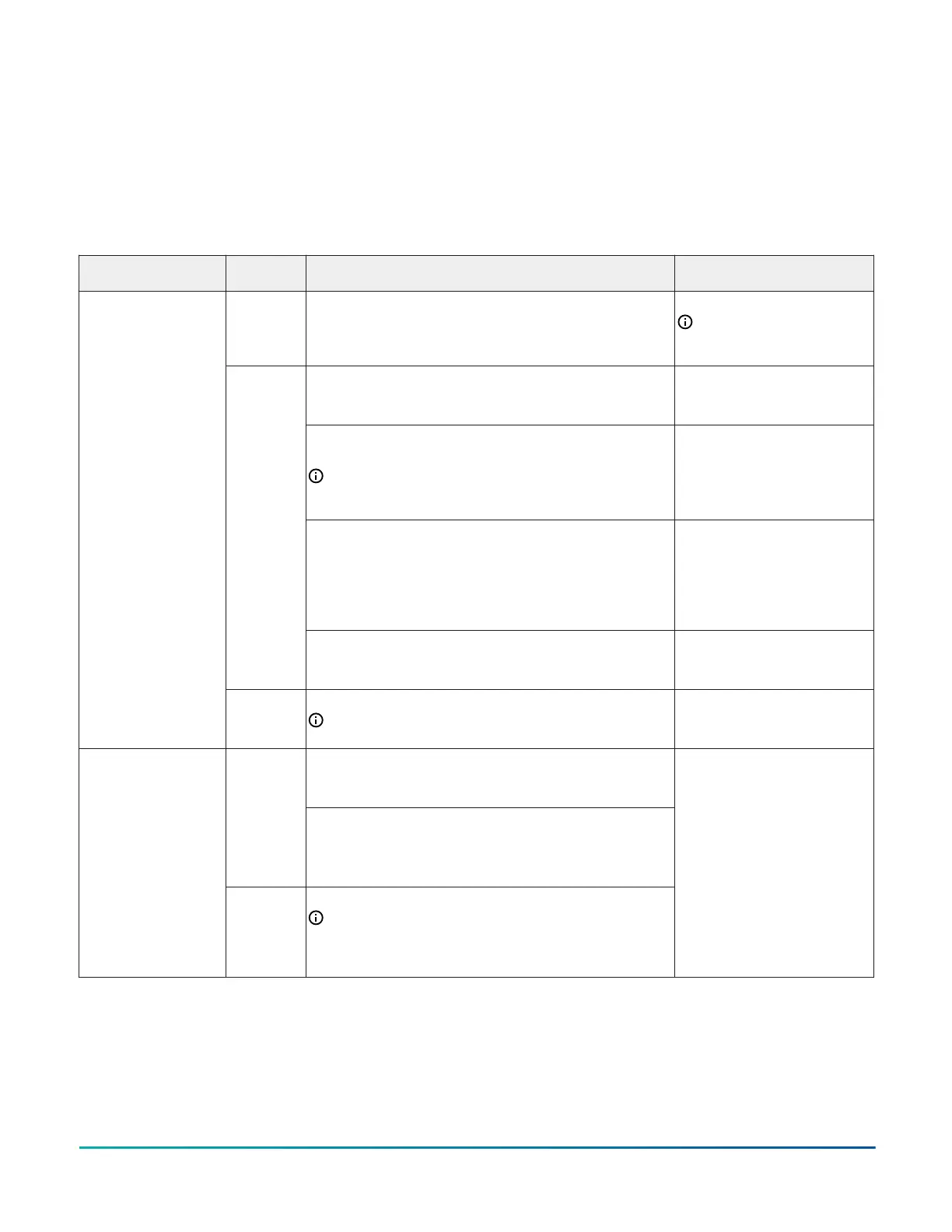
I/O terminal block functions, ratings, and requirements
Table 3: I/O terminal block functions, ratings, requirements, and cable guidelines
Terminal Block label
Terminal
label
Function, ratings, requirements
Determine wire size and
maximum cable length
+15 V
15 VDC Power Source for active (3-wire) input devices
connected to the Universal UI-n terminals.
Provides 100 mA total current
Same as (Universal) UI-n
Note: Use 3-wire cable for
devices that source power
from the +15V terminal.
Analog Input - Voltage Mode (0–10 VDC)
10 VDC maximum input voltage
Internal 10k ohm Pull-down
See Guideline A in Table 4
Analog Input - Current Mode (4–20 mA)
Internal 100 ohm load impedance
Note: Current loop jumpers must be in the Enabled
position to maintain a closed 4-20 mA current loop. See
Setting the UI current loop jumpers.
See Guideline B in Table 4.
Analog Input - Resistive Mode (0–600k ohm)
Internal 12 V. 15k ohm pull up
Qualified Sensors: 0-2k ohm potentiometer, RTD (1k Nickel
[Johnson Controls
®
sensor], 1k Platinum, and A99B Silicon
Temperature Sensor) Negative Temperature Coefficient (NTC)
Sensor
See Guideline A in Table 4.
UI-n
Binary Input - Dry Contact Maintained Mode
1 second minimum pulse width
Internal 12 V. 15k ohm pull up
See Guideline A in Table 4.
UNIVERSAL
(Inputs)
UI-C or UI-
Cn
Universal Input Common for all Universal Input terminals
Note: All Universal UI-C or UI-Cn terminals share a
common, which is isolated from all other commons.
Same as (Universal) UI-n
Binary Input - Dry Contact Maintained Mode
0.01 second minimum pulse width
Internal 18 V. 3k ohm pull up
BI-n
Binary Input - Pulse Counter/Accumulator Mode
0.01 second minimum pulse width
(50 Hz at 50% duty cycle)
Internal 18 V. 3k ohm pull up
BINARY
(Inputs)
BI-C or BI-
Cn
Binary Input Common for all Binary Input terminals
Note: All Binary BI-C or BI-Cn terminals share a
common, which is isolated from all other commons,
except the Configurable Output (CO) common when the
CO is defined as an Analog Output.
See Guideline A in Table 4.
M4-CGM General Purpose Application Controller Installation Guide6