Firmware Version 3.5 Factory Field Installation
24-10025-199 Rev. –
4
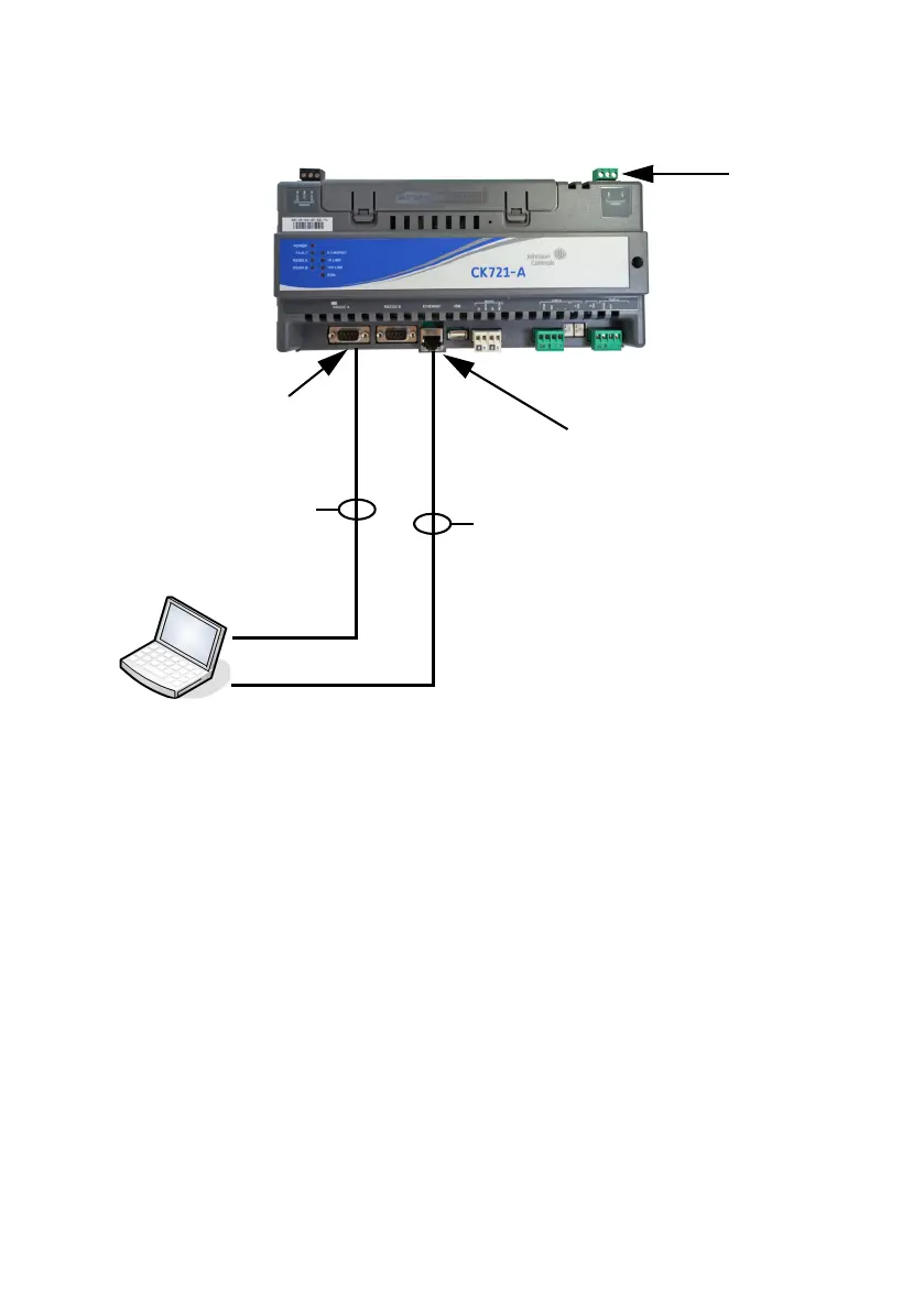
Figure 1: Connections between Computer and CK721-A Controller
2. Connect one end of the Ethernet cable to the network port of the
computer or to a USB to Ethernet adapter. Connect the other end of
the cable to the Ethernet port CK721-A controller.
C
OMPUTER CONFIGURATION
Once you have properly connected the computer to the CK721-A controller,
you are ready to configure the computer as follows:
• Enable file and printer sharing for Microsoft networks
• Set the computer’s IP address to 192.168.2.1, and subnet mask to
255.255.255.0.
• Disable computer firewall software
Computer
CK721-A Controller
RS232 Null Modem
Cable (DB9F/F)*
COM 1 or 2**
Ethernet
RS232C A
Serial Port
Ethernet Port
10/100Base-T CAT5 Ethernet
Crossover Cable*
(Use straight-through Ethernet cables
if connecting to CK721-A via a hub/
switch or with most laptop computers.)
Power
* Maximum Distance: 15 m (50 ft.)
** Baud Rate: 115200

 Loading...


