Communications bus and supply power terminal blocks, ratings, and requirements
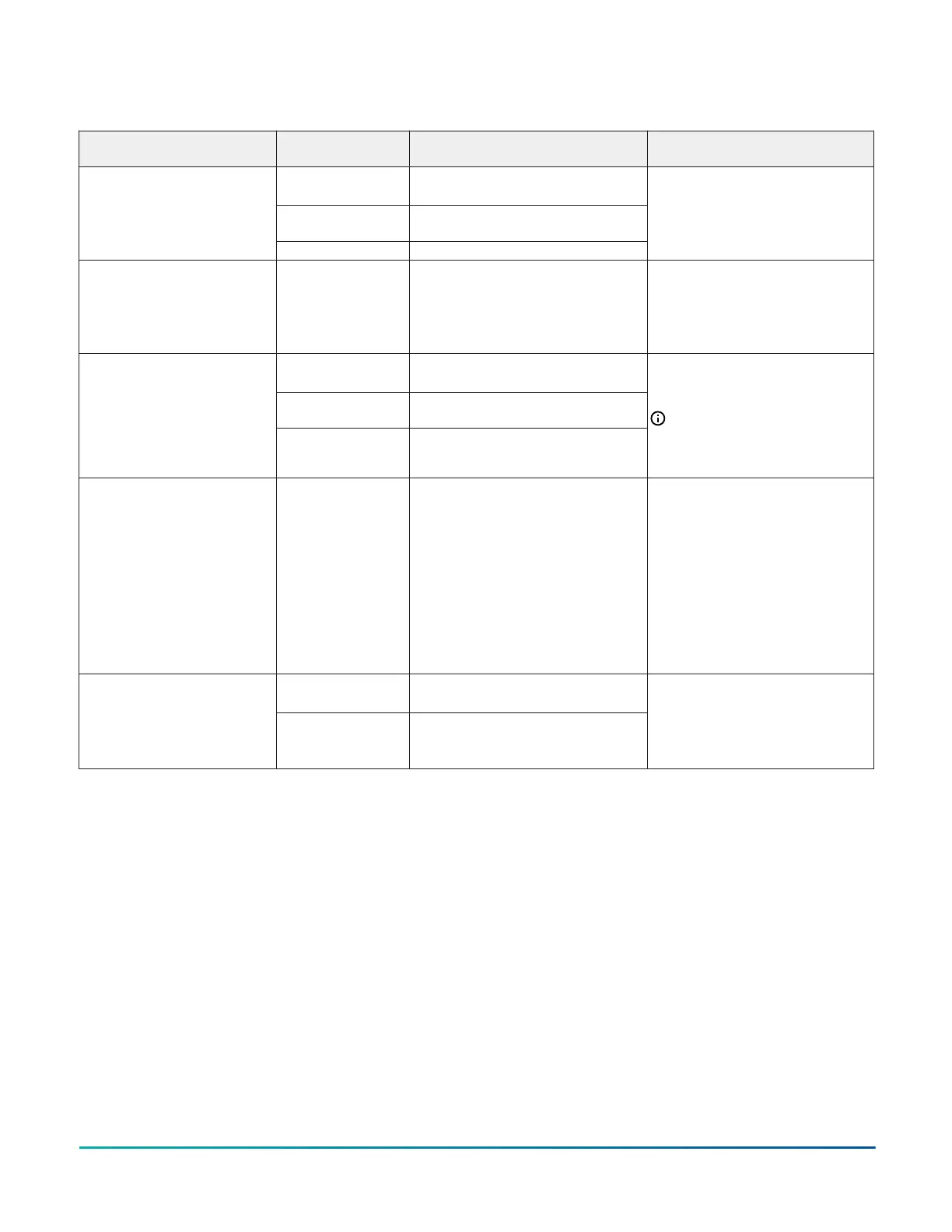
Table 7: Communication bus and supply power terminal blocks, functions, ratings, requirements, and cables
Terminal block/Port label Terminal labels
Function, electrical ratings/
Requirements
Recommended cable type
+
-
FC Bus Communications
COM
Signal Reference (Common) for bus
communications
FC BUS
11
SHD Isolated terminal
0.6 mm (22 AWG) stranded, 3-wire
twisted, shielded cable recommended
FC BUS (Port)
1
FC BUS
RJ-12 6-Position Modular Port provides
FC Bus Communications.
FC Bus provides 15 VDC Power for:
• MAP Gateway
• Wireless ZigBee Field Bus Router
24 AWG 3-pair CAT 3 Cable <30.5m
(100 ft)
+
-
SA Bus Communications
COM
SA Bus Signal Reference and 15 VDC
Common
SA BUS
1
POWER
15 VDC Supply Power for Devices on the
SA Bus
0.6 mm (22 AWG) stranded, 4-wire
(2 twisted-pairs), shielded cable
recommended
Note: The + and - wires are one
twisted pair, and the COM and
POWER wires are the second
twisted pair.
SA BUS (Port)
1
SA BUS
RJ-12 6-Position Modular Port provides
SA Bus Communications.
SA Bus provides 15 VDC Power for the
following:
• NS Series Sensors
• MAP Gateway 4.2 or above
• Wireless ZigBee FX-ZFR-7860
Series One-to-One Wireless
Receiver
• DIS1710 Local Controller Display
• VAV Balancing Tool
24 AWG 3-pair CAT 3 Cable <30.5m
(100 ft)
HOT
24 VAC Power Supply - Hot
Supplies 20–30 VAC (Nominal 24VAC)
24V~
COM
24 VAC Power Supply Common
The CVM models only isolate this
terminal from the FC bus common.
0.8 mm to 1.0 mm
(20 to 18 AWG) 2-wire
1 The FC bus and SA bus wiring recommendations in this table are for MS/TP Bus communications at 38.4k baud.
F4-CV Series VAV Terminal Equipment Controllers Installation Guide10
 Loading...


