Installation
Observe the following guidelines when installing a CVM
controller:
• To minimize vibration and shock damage to the
controller, transport the controller in the original
container.
• Verify that all parts shipped with the controller.
• Do not drop the controller or subject it to physical
shock.
Parts included
• One CVM03050 controller with removable terminal
blocks (Input/Output, Power, FC, and SA terminal blocks
bus are removable)
• One installation instructions sheet
• One self-drilling No. 10 x 25 mm (1 in.) screw
Materials and special tools needed
• Small, straight-blade (1/8 in. or 3.2mm) or Phillips #2
screwdriver for securing wires in the terminal blocks
• 8 mm (5/16 in.) wrench or 10 mm (3/8 in.) 12-point
socket to tighten the square coupler bolt
• Several shims or washers to mount the CVM
• Power screwdriver, 100 mm (4 in.) extension socket,
punch, drill, and 3.5 mm (9/64 in.) drill bits to mount the
CVM
• Pliers to open and close the damper
• Required length of 3.97 mm (5/32 in.) ID pneumatic
tubing and barbed fittings
Physical features
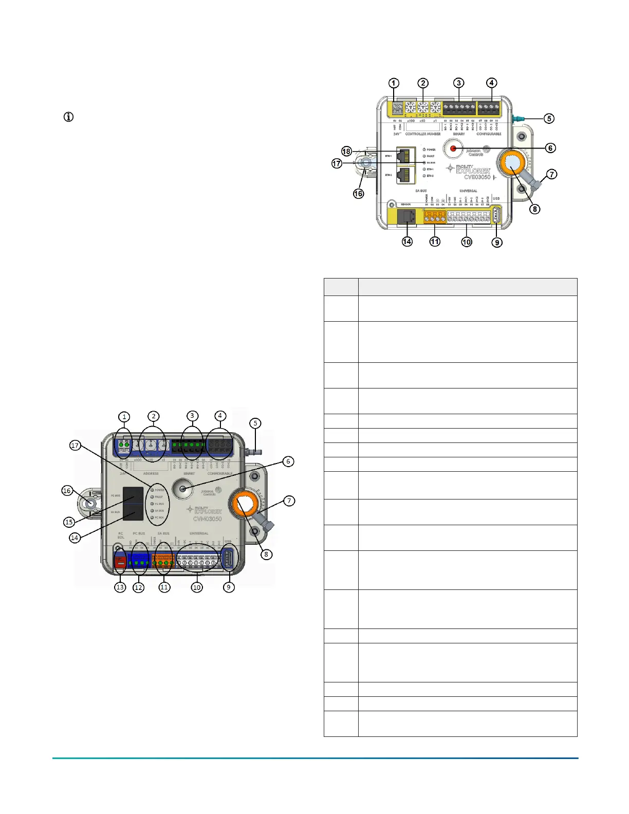
The following figure displays the physical features of
CVM03050, and the accompanying table provides a
description of the physical features and a reference to
further information where required.
Figure 2: CVM03050 physical features
Table 1: CVM03050 physical features
Physical features: description and references
1
Supply Power Terminal Block: Gray terminals. See
Supply power terminal block.
2
Device Address Rotary Switches: decimal addressing.
See Setting the device address.
3
Binary Output (BO) Terminal Block: Black terminals.See
Table 5.
4
Configurable Outputs (CO) Terminal Block: Black
terminals. See Table 5.
5 Dual Port Fitting.
6 Manual Override Button. See Mounting.
7 Coupler Bolt
8 Controller Coupler. See Mounting.
9
Universal Serial Bus (USB) 2.0 Host Type A Port
Note: The USB feature is not currently supported.
10
Universal Inputs (UI) Terminal Block: White terminals.
See Table 5.
11
Sensor Actuator (SA) Bus Terminal Block: Orange
terminal. See SA bus terminal block.
12
Field Controller (FC) Bus Terminal Block: Blue terminal;
may also be used for N2 connections, see FC bus
terminal block (or N2 protocol as required).
13
EOL (End-of-Line) Switch. See Setting the End-of-Line
(EOL) switch.
14
SA Bus Port: RJ-12 6-Pin Modular Jack. See Modular
ports.
15
FC Bus Port: RJ-12 6-Pin Modular Jack. See Modular
ports.
16 Captive Spacer and Screw.
17 LED Status Indicators. See LED Table.
Mounting
Observe the following guidelines when mounting a CVM
controller:
• Ensure that the mounting surface can support the CVM
and any user-supplied enclosure.
• Mount the CVM on a hard, even surface whenever
possible.
• Use shims or washers to mount the CVM securely and
evenly on the mounting surface.
• Mount the CVM in an area free of corrosive vapors
that matches the ambient conditions specified in the
Technical specifications section.
• Provide sufficient space around the CVM for cable and
wire connections and adequate ventilation through the
controller (at least 50 mm [2 in.] on the top, bottom,
sides, and front of the controllers).
• Do not mount the CVM in areas where electromagnetic
emissions from other devices or wiring can interfere
with controller communication.
• Avoid mounting the CVM on surfaces with excessive
vibration.
F4-CV Series VAV Terminal Equipment Controllers Installation Guide2
 Loading...


