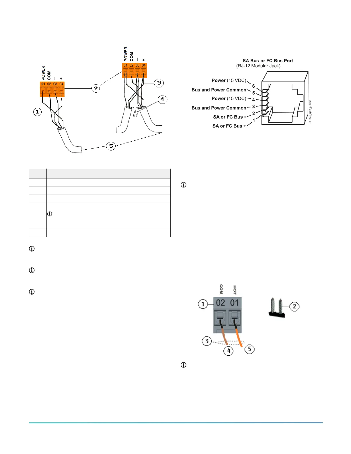
Figure 7: Pin number assignments for FC bus and SA
ports on equipment controllers
The modular SA Bus port provides a connection for the
MAP Gateway, ATV7003 VAV Balancing Tool , FX-DIS1710
Local Controller Display, FX-WRZ78xx Series One-to-One
Wireless Transmitter, and NS Series sensors. The modular
FC Bus port provides a connection for the Bluetooth
Commissioning Converter and the FX-ZFR Wireless Router.
Note: Do not use the modular SA Bus port and the
terminal block SA Bus simultaneously. Only use one
of these connections at a time.
Supply power terminal block
The 24 VAC supply power terminal block is a gray,
removable, 2-pin terminal block that fits into a board-
mounted pin header on the upper left of the CVM03050
controller.
Wire the 24 VAC supply power wires from the transformer
to the HOT and COM terminals on the terminal block as
shown in Figure 8. For more information about Supply
Power terminal functions, requirements, and ratings, see
Table 7.
Figure 8: 24 VAC supply power terminal block wiring
Table 4: Supply power terminal block wiring
Description
1 Supply power terminal block
2 Supply power terminal header
3
Wires from Johnson Controls 24 VAC, class 2 power
transformer
4 COM (Brown wire)
5 24 VAC (Orange wire)
Note: The supply power wire colors may be different
on transformers from other manufacturers. Refer to
the transformer manufacturer’s instructions and the
project installation drawings for wiring details.
Important: Connect 24 VAC supply power to
the CVM and all other network devices so that
transformer phasing is uniform across the network
devices. Powering network devices with uniform
24 VAC supply power phasing reduces noise,
interference, and ground loop problems. The CVM
does not require an earth ground connection.
However, when grounding the secondary of the 24
VAC transformer is required, only one connection
to ground must be made near the transformer. See
Figure 9.
Figure 9: Transformer grounding
CAUTION
Risk of Property Damage:
Do not apply power to the system before checking all
wiring connections. Improper wiring of this terminal
may cause a short circuit across the 24 VAC power
supply. A short circuit may result in a tripped circuit
breaker or blown fuse. If using a transformer with a
built-in fuse, the transformer may need to be replaced.
F4-CV Series VAV Terminal Equipment Controllers Installation Guide6
 Loading...


