RWH ROTARY SCREW COMPRESSOR UNITS
INSTALLATION
070.620-IOM (DEC 12)
Page 14
NOTICE
If starting methods other than across-the-line are de-
sired, a motor/compressor torque analysis must be done
to ensure that sufcient starting torque is avail able,
particularly in booster applica tions. Contact Johnson
Controls-Frick if assistance is required.
2. If specied, the starter package can be supplied as a
combination starter with circuit breaker disconnect. Howev er,
the motor overcurrent protection/disconnection device can
be applied by others, usually as a part of an electrical power
distribution board.
3. The oil pump starter with fuses, or in the case where the
compressor motor is a different voltage from the oil pump
motor, with a circuit breaker disconnect suitable for sepa rate
power feed.
4. A properly sized control power transformer (CPT) to
supply 120 volt control power to the microprocessor control
system and separator oil heaters is included. If environ mental
condi tions require more than the usual 1000 watt oil heat
ers, an appropriately oversized control transformer will be
required. If frequent power uc tuations are anticipat ed or
extremely noisy power lines are encoun tered, a regulating
control transformer should be considered. Contact Johnson
ControlsFrick
®
for assistance.
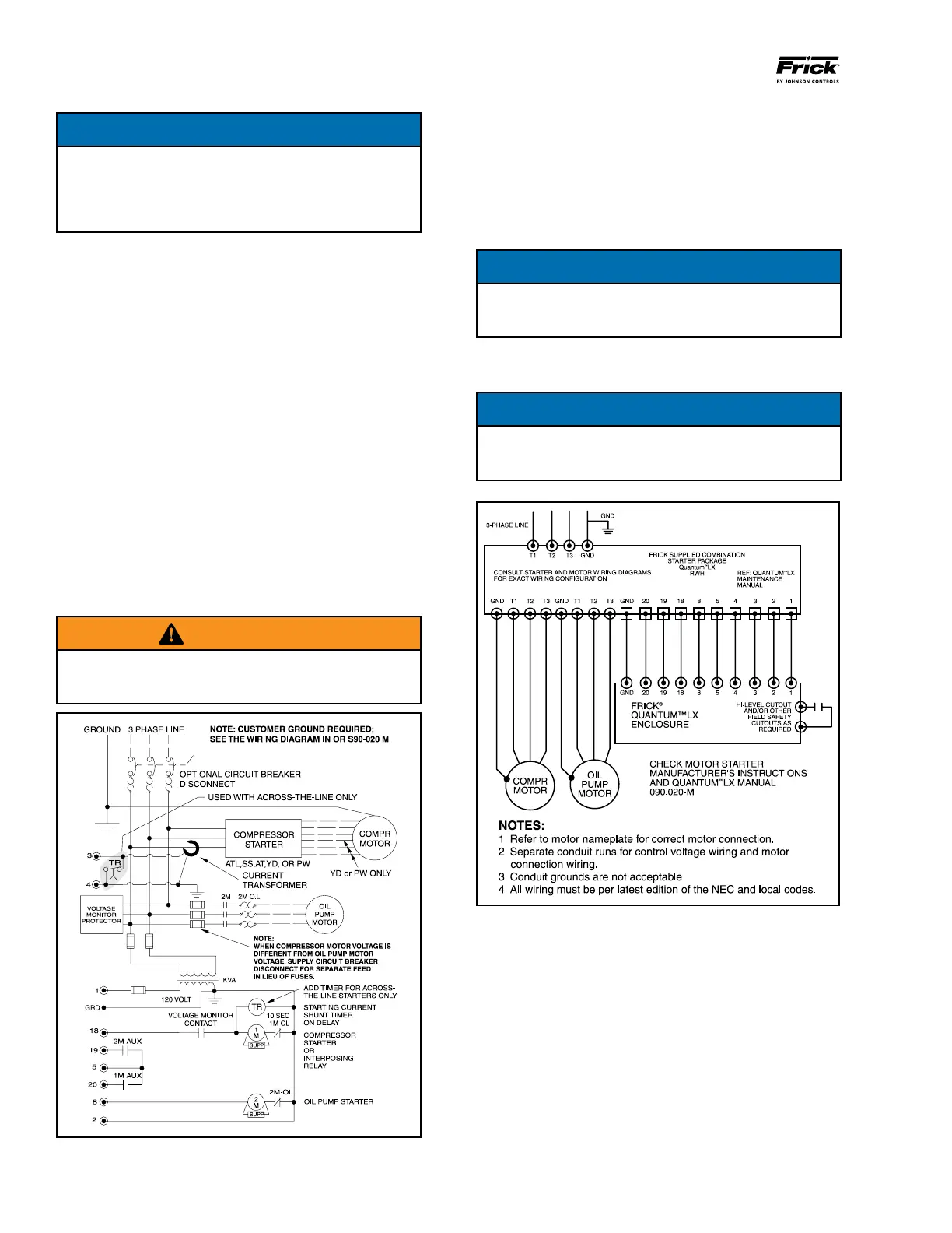
5. For customersupplied acrosstheline starters, a shunt
ing device must be installed across the Current Transformer
(terminals 3 & 4).
WARNING
If the shunting device is not installed, the Analog I/O
board on the Quantum
™
LX panel may be severely dam-
aged at start-up. See Figure 17.
Figure 17 - Starter Wiring Diagram
6. One each normally open compressor motor and oil pump
motor starter auxiliary contact should be supplied. In addition
to the compressor and oil pump motor starter coils, the CT
and CPT secondaries should be wired as shown on the starter
package wiring diagram. The load on the control panel for
the compressor motor starter coil should not exceed a 2 amp
load. For larger starters, an interposing relay must be used
to switch the compres sor motor starter coil(s).
NOTICE
Do not install a compressor HAND/OFF/AUTO switch in
the starter package as this would bypass the compres-
sor safety devices.
7. The compressor motor Current Transformer (CT) is in
stalled on any one phase of the compressor leads.
NOTICE
The CT must see all the current of any one phase,
therefore in wye-delta applications BOTH leads of any
one phase must pass through the CT.
Figure 18 - Point-To-Point Wiring Diagram