RXF ROTARY SCREW COMPRESSOR UNITS
MAINTENANCE
070.410-IOM (JAN 12)
Page 33
an allowance in the readings must be made by subtracting
approximately 0.02 VDC per 1000 feet of elevation above
sea level. Barometric pressure can generally be ignored but
in extreme cases may be compensated for by adding/sub-
tracting 0.002 VDC for each 0.1 inch of barometric pressure
(adjusted to sea level) above/below 0 PSIG. Therefore, if
(PE-4) is measured at 5000 feet elevation under relatively
normal weather conditions, the output voltage should differ
by 0.10 VDC to read between 1.38 VDC and 1.62 VDC.
5. Subtract 1 from the voltage.
6. Multiply by 25.
7. This result is the absolute suction pressure (PSIA). Subtract
14.7 to obtain PSIG which the Operating display will indicate.
8. Isolate the oil pressure transducers (PE-1 & PE-2) from
the package and depressurize. NOTE: Recover or transfer
all refrigerant vapor, in accordance with local ordinances,
before opening to atmosphere.
9. Measure the voltage of (PE-1 & PE-2) on connector (P5A)
(terminals 5 and 6) on the analog board.
10.
The voltage reading should be between 1.1 VDC and 1.29
VDC at standard atmospheric pressure. (PE-1
& PE-2
) and
(PE-3) have a span of 500 PSI as compared to (PE-4) with a
span of 200 PSI. Therefore, atmospheric pressure changes
have a lesser effect which is 0.0067 VDC per 1000 feet of
eleva tion and 0.00067 VDC per 0.1 inch Hg baro metric de-
viation.
11. Subtract 1.2 from the voltage.
12. Multiply by 75, the result will be PSIG.
13.
Since the discharge pressure (PE-3) cannot be closed
off from its sensing point (code require ments), remove all
transducers from atmosphere and open them to their sensing
points so all transducers can equalize to separator pressure.
14. Measure the voltage of (PE-3) on connector (P5B) (ter-
minals 5 and 6) on the analog board.
15. Test complete.
PRESSURE TRANSDUCERS REPLACEMENT
1. Shut off control power.
2. Close the applicable transducer isolation valve. NOTE: To
change the discharge pressure transducer ( PE-3), it will be
necessary to depressurize the entire compressor package.
Follow "General Instructions For Replacing Compressor Unit
Components" section before going to step 3.
3. Remove DIN connector screw, then remove DIN connector
from the transducer.
TRANSDUCER CONNECTION
Suction Pressure PE-4
Discharge Pressure PE-3
Oil Pressure PE-1 & PE-2
4. Unscrew the transducer using a wrench on the metal hex at
the base of the transducer. DO NOT ATTEMPT TO LOOSEN
OR TIGHTEN TRANSDUCERS BY THEIR TOP CASING.
5. Install new transducer, reconnect DIN connector, and
retighten DIN connector screw.
6. Recalibrate. NOTE: If replacing older hard-wired trans-
ducer, cut cable at back of old transducer and rewire to
the Danfoss unit.
7. Reopen the transducer isolation valve or compressor pack-
age isolation valves.
8. Turn on control power.
SLIDE VALVE TRANSMITTER
REPLACEMENT - SLIDE STOP
The Slide Valve Transmitter (Figure 34) is located on the
right side of the compressor (facing shaft) at the inlet end.
The linear transmitter with hermetic enclosure is based on
the inductive measuring principle. It features removable
electronics (from the sensor well) eliminating the need to
evacuate the compressor for replacement. This type of
transmitter is dedicated to volume ratio control and has no
user adjustments.
1. Shut off control power.
2. Remove DIN connector plug from transmitter.
3. Loosen set screws.
4. Remove transmitter unit.
5. Install new transmitter unit.
6. Tighten set screws.
7. Apply DIN connector plug to transmitter.
8. Turn on control power.
NOTE: For calibration of the Slide Valve unit, refer to the
Analog Calibration instructions in publication 090-020 O.
Figure 34 - Slide Valve Transmitter
TEMPERATURE SENSOR REPLACEMENT
This device is static sensitive. Please
follow proper ESD procedures when
handling.
1. Shut off control power.
2.
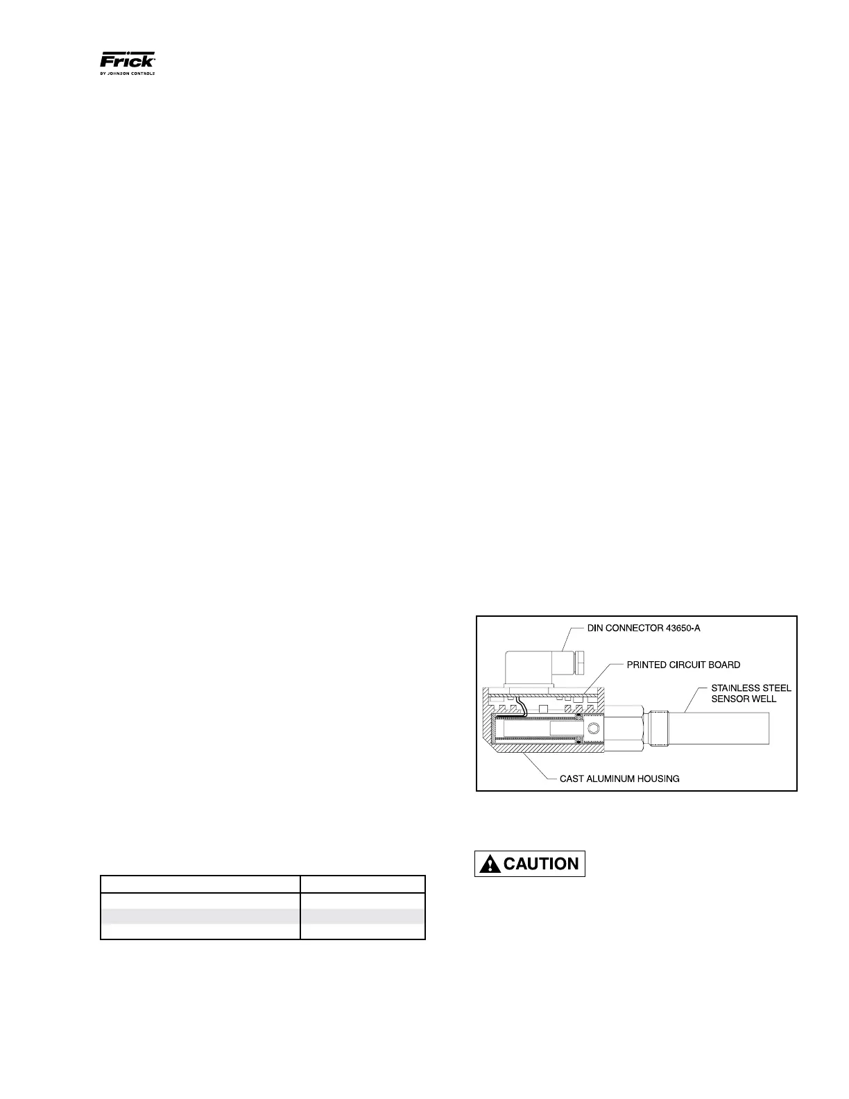
Remove DIN connector plug from transmitter. See Figure 35.
3. Unscrew knurled ring and remove transmitter unit.
4. Apply thermal compound to new sensor assembly, insert
into thermal well, and tighten knurled ring.
5. Apply DIN connector plug to transmitter.
6. Turn on control power.