RXF ROTARY SCREW COMPRESSOR UNITS
INSTALLATION
070.410-IOM (JAN 12)
Page 6
COMPRESSOR/MOTOR COUPLINGS
RXF units are arranged for direct motor drive and include a
exible drive coupling to connect the compressor to the motor.
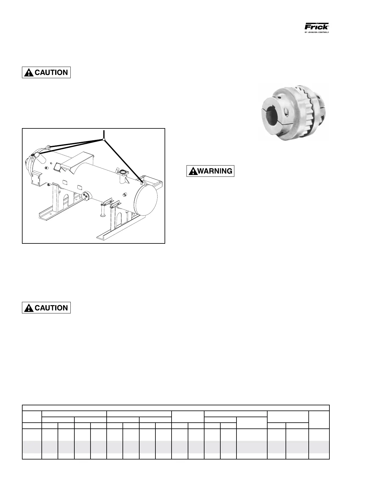
CH COUPLING
The T. B. Woods Elastomeric Type
CH Coupling is used in most appli-
cations. This coupling consists
of two drive hubs and a gear-
type Hytrel, EDPM, or neo-
prene drive spacer. The split
hub is clamped to the shaft by
tightening the clamp screws.
Torque is transmitted from the
motor through the elastomeric
gear which oats freely between the
hubs. Because of the use of the motor/compressor adapter
housing on the RXF, no eld alignment is necessary.
It is mandatory that the coupling
center be removed and the direction
of motor rotation be confirmed
before running the compressor. Proper rotation of the
compressor shaft is clockwise looking at the end of the
compressor shaft. Failure to follow this step could result
in backward compressor rotation which can cause com-
pressor failure or explosion of the suction housing.
1. Inspect the shaft of the motor and compressor to ensure
that no nicks, grease, or foreign matter is present.
2. Inspect the bores in the coupling hubs to make sure that
they are free of burrs, dirt, and grit.
3. Check that the keys t the hubs and shafts properly.
4. Slide one hub onto each shaft as far as possible. It may
be necessary to use a screwdriver as a wedge in the slot to
open the bore before the hubs will slide on the shafts.
5. Hold the elastomeric gear between the hubs and slide both
hubs onto the gear to fully engage the mating teeth. Center
the gear and hub assembly so there is equal engagement on
both shafts. Adjust the space between hubs as specied in
the CH Coupling Data Table below. NOTE: The center sec-
tion will be a little loose between the hubs. This allows
for growth during operation.
6. Torque the clamping bolts in both hubs to the torque value
given in the CH Data Table. DO NOT USE ANY LUBRICANT
ON THESE BOLTS.
HOLDING CHARGE and STORAGE
Each compressor unit is pressure and leak tested at the John-
son Controls-Frick factory and then thoroughly evacuated and
charged with dry nitrogen to ensure the integrity of the unit
during shipping and short term storage prior to installation.
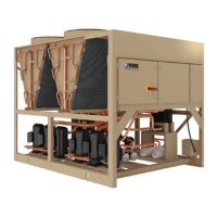
RXF 58 – 101 units can be moved with rigging, using a crane
or forklift by hooking into three lifting points on the oil sepa-
rator. See Figure 2.
Spreader bars may be required on
both the length and width of the
package to prevent bending oil lines
and damage to the package. CAUTION must also be used
in locating the lifting ring. Appropriate adjust ment in the
lifting point should be made to compensate for motor
weight. Adjustment of the lifting point must also be made
for any additions to the standard package such as an
external oil cooler, etc., as the center of balance will be
affected.
Figure 2 - RXF 58 – 101
The unit can be moved with a forklift by forking under
the wooden skid (if provided), or it can be skidded into
place with pinch bars by pushing against the skid. NEVER
MOVE THE UNIT BY PUSHING OR FORKING AGAINST THE
SEPARAT OR SHELL OR ITS MOUNTING SUPPORTS.
SKID REMOVAL
This screw compressor package may
be top-heavy. Use caution to pre-
vent unit from turning over.
If the unit is rigged into place, the wooden skid can be re-
moved by taking off the nuts and bolts that are fastening the
unit mounting supports to the skid before lowering the unit
onto the mounting surface.
If the unit is skidded into place, remove the cross mem bers
from the skid and remove the nuts anchoring the unit to the
skid. Using a 10-ton jack under the separator, raise the unit
at the compressor end until it clears the two mounting bolts.
Spread the skid to clear the unit mounting support, then lower
the unit to the surface. Repeat proced ure on opposite end.
CH COUPLING DATA TABLE
Coupling Hub
CH Between Shaft Spacing Shaft Engagement
Face
Spacing
Clamp Bolt Keyway
Series
Min. Max. Min. Max.
Torque (Dry)
Size
Setscrew Torque Size
Size In. mm In. mm In. mm In. mm In. mm Ft-Lb Nm Ft-Lb Nm
UNC
6 2 50.8 2¾ 69.9 1 25.4
1ZB\zn
49.2 7/8 22.2 15 20.3 1/4-20 UNC 13 17.6 5/16-18
7
2B\zn
58.7
3M\zn
87.3 1 25.4
2C\zn
55.6
1Z\zn
27.0 30 40.7 5/16-24 UNF 13 17.6 5/16-18
8
2>\zn
65.1 4 101.6
1Z\zn
27.0 2½ 63.5
1Z\,
28.6 55 74.6 3/8-24 UNF 13 17.6 5/16-18
9
3Z\zn
77.8
4B\,
117.5
1M\zn
36.5 3 76.2
1M\zn
36.5 55 74.6 3/8-24 UNF 13 17.6 5/16-18
10
3>\zn
90.5 5¼ 133.4
1ZZ\zn
42.9 3½ 88.9
1ZZ\zn
42.9 130 176.3 1/2-20 UNF 13 17.6 5/16-18
 Loading...