RXF ROTARY SCREW COMPRESSOR UNITS
INSTALLATION
070.410-IOM (JAN 12)
Page 12
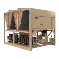
Motor starter and interlock wiring require ments are shown
in the diagram, Figure 12. All of the equipment shown is sup-
plied by the installer unless a starter package is pur chased
separately from Frick. Starter packages should consist of:
1. The compressor motor starter of the specied horse-
power and voltage for the starting method specified
(across-the-line, autotransformer, wye-delta or solid-state).
NOTE: If starting methods other than across-the-line are
desired, a motor/compres sor torque analysis must be done
to ensure sufcient starting torque is available. Contact
Frick if assist ance is required.
2. If specied, the starter package can be sup plied as a com-
bination starter with circuit breaker disconnect. How ever,
the motor overcurrent protection/discon nec tion device can
be applied by others, usually as a part of an electrical power
distribution board.
3. A 3.0 KVA control power transformer (CPT) to supply 120
volt control power to the control system and separator oil
heaters is included. If environmental conditions require more
than 2000 watts of heat, an appro priately oversized control
trans former will be required.
4. One normally open compressor motor starter auxiliary
contact should be supplied and wired as shown on the starter
package wiring diagram. In addition, the compressor starter
coil and the CPT secondaries should be wired as shown on
the starter package wiring diagram, Figure 12.
Figure 13 - Point-to-Point Wiring Diagram
5. The compressor motor Current Transformer (CT) can be
installed on any one phase of the compressor leads. NOTE:
the CT must see all the current on any one phase, there-
fore in wye-delta applications BOTH leads of any one
phase must pass through the CT.
CURRENT TRANSFORMER SIZE
Calculate (CT) size using the following formula where SF is
Service Factor and FLA is Full Load Amps of the Motor.
FLA x SF x 1.1
(round up to the next hundred)
Example: FLA = 379; Service Factor = 1.15
379 x 1.15 x 1.1 = 479
Use a 500:5 CT
DO NOT use undersized current transformers since the panel
will not be capable of reading potential current. If the CT is
higher than calculated, enter it's value for [CT Factor] on the
panel. The unit can operate with a CT one size larger than
calculated, however, replace with the proper size ASAP. DO
NOT operate unit with a CT more than one size larger
than recommended.
MINI MUM BURDEN RATINGS
The following table gives the minimum CT burden ratings.
This is a function of the distance between the motor starting
package and the compressor unit.
B-0.1 2.5 15 ft 25 ft 40 ft
B-0.2 5 35 ft 55 ft 88 ft
B-0.5 12.5 93 ft 148 ft 236 ft
NOTE: Do not install a compressor HAND/OFF/AUTO
switch in the starter package as this would bypass the
compressor safety devices.
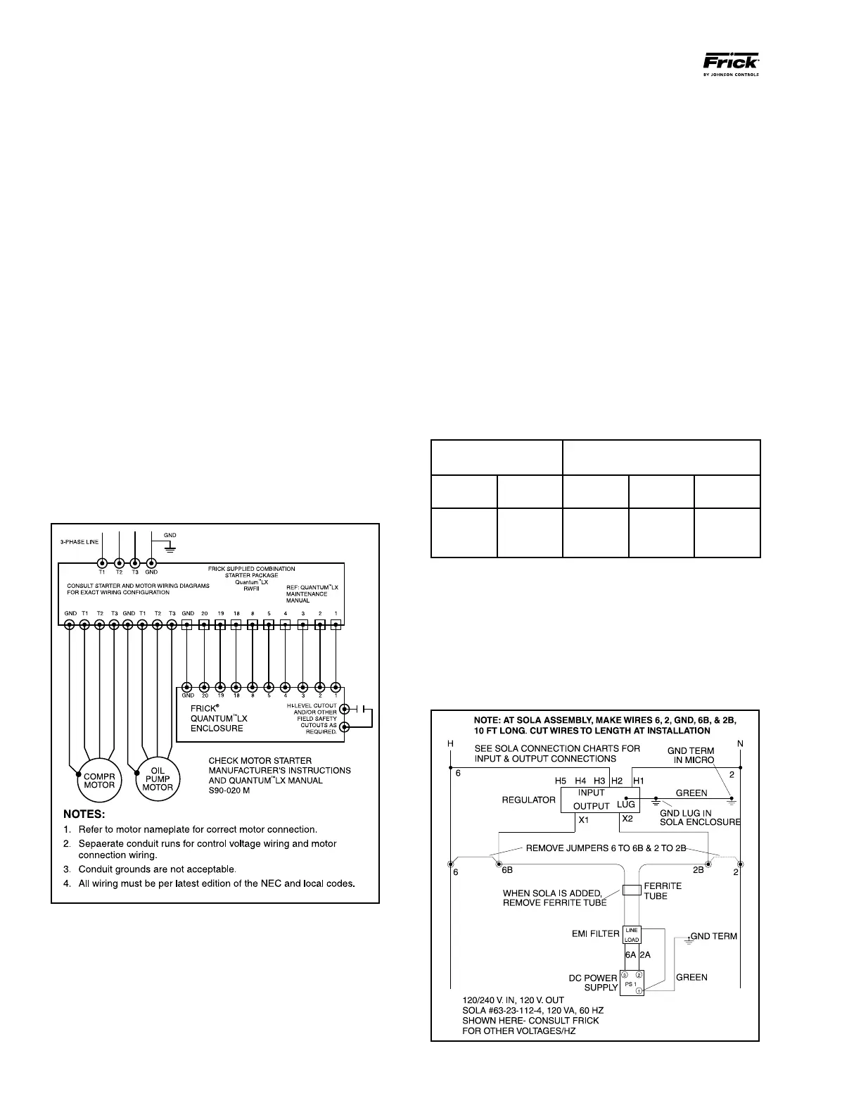
CONTROL POWER REGULATOR
Compressor units that will be used in areas that suffer brown-
outs and other signicant power uctuations can be supplied
with a control power regulator. See Figure 14, Recommended
Regulator Installation.
Figure 14 - Recommended Regulator Installation
 Loading...