RXF ROTARY SCREW COMPRESSOR UNITS
INSTALLATION
070.410-IOM (JAN 12)
Page 11
Other than the isolation valve
needed for strainer cleaning, it
is essential that the strainer be the
last device in the economizer line before the compres sor.
The strainer must be strong enough to handle the gas
pulsations from the compressor. Johnson Controls-Frick
recommends an R/S or Hansen strainer. Also, piston-type
check valves are recom mended for installation in the
economizer line, as opposed to disc-type check valves.
The latter are more prone to gas-pulsation-induced fail-
ure. The isolation and check valves and strainer should
be located as closely as possible to the compressor, pref-
erably within a few feet.
For refrigeration plants employing multiple compressors on
a common economizing vessel, regardless of economizer
type, each compressor must have a back-pressure regulat-
ing valve in order to balance the economizer load, or gas
ow, between compressors. The problem of balancing load
becomes most important when one or more compressors
run at partial load, exposing the economizer port to suction
pressure. In the case of a ash vessel, there is no need for
the redundancy of a back-pressure regulating valve on the
vessel and each of the multiple compressors. Omit the BPR
valve on the ash economizer vessel and use one on each
compressor, as shown in Figure 12.
ELECTRICAL
NOTE: Before beginning electrical installation, read the
instructions in the section "Proper Installation of Elec-
tronic Equipment" at the back of this manual.
RXF units are supplied with a Quantum
™
LX control system.
Care must be taken that the controls are not exposed to
physical damage during handling, storage, and installa tion.
The single-box control door must be kept tightly closed to
prevent moisture and foreign mat ter from entry.
Customer connections are made in
t h e Q u a n t u m
™
L X c o n t r o l
panel* mounted on the unit. The
electrical enclosures should be kept tightly closed when-
ever work is not being done inside. * Or starter panel (if
provided).
VOLTAGE PROTECTION
Frick
®
does not advise nor support the use of UPS
power systems in front of the Quantum
™
LX panel. With
a UPS power system providing shutdown protection for the
Quantum
™
LX, the panel may not see the loss of the 3-phase
voltage on the motor because the UPS could prevent the
motor starter contactor from dropping out. With the starter
contactor still energized, the compressor auxiliary will con-
tinue to feed an “Okay” signal to the panel. This will allow
the motor to be subjected to a fault condition on the 3-phase
bus. Some fault scenarios are:
1. The 3-phase bus has power “on” and “off” in a continu-
ous cyclic manner which may cause the motor to overheat
due to repeated excessive in-rush currents.
2. Motor cycling may damage the coupling or cause other
mechanical damage due to the repeated high torque motor
“bumps”.
3.
Prolonged low voltage may cause the motor to stall and
overheat before the motor contactor is manually turned off.
Under normal conditions, the loss of 3-phase power will shut
down the Quantum
™
LX panel, and it will restart upon power
return. If the panel was in:
• Auto – Compressor motor will return to running as pro-
grammed.
• Remote – The external controller would reinitialize the
panel and proceed to run as required.
• Manual – The compressor will have to be restarted
manually after the 3-phase bus fault has been cleared.
If the local power distribution system is unstable or prone
to problems, there are other recommendations to satisfy
these problems. If power spikes or low or high line voltages
are the problem, then Frick
®
recommends the use of a Sola
®
constant voltage (CV) transformer with a line suppression
feature. If a phase loss occurs, then you will typically get a
high motor amp shutdown. If problems continue to exist, then
an examination of the plant’s power factor may be in order.
Unless careful design failure analysis is considered in the
implementation of power systems, the alternative solutions
provide a safer and less expensive implementation. In either
case, only one Sola
®
may be used per compressor. Each
compressor needs to be individually isolated from each other
through a dedicated control transformer. Sharing a common
control power source is an invitation for ground loops and
the subsequent unexplainable problems.
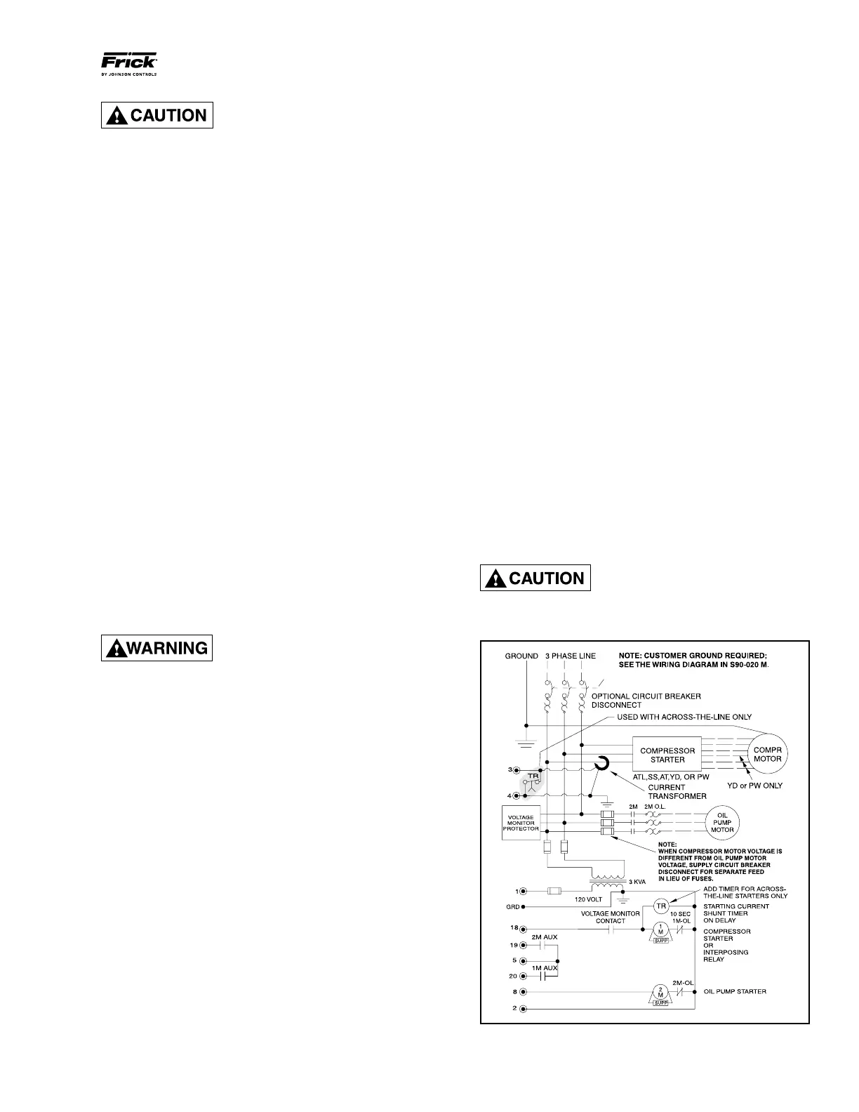
MOTOR STARTER PACKAGE
When starting at full voltage or
across-the-line, a shunting device
must be installed or the Analog I/O
board in the Quantum
™
LX panel may be severely damaged
at start-up. See Figure 12.
Figure 12 - Starter Wiring Diagram
 Loading...