RXF ROTARY SCREW COMPRESSOR UNITS
MAINTENANCE
070.410-IOM (JAN 12)
Page 34
NOTE: For calibration instructions, refer to Quantum™ LX
Operator's Manual 090-020 O, -021 O, -022 O.
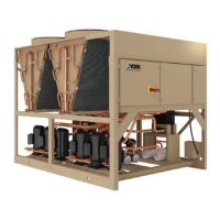
Figure 35 - Temperature Transmitter
OIL LEVEL TRANSMITTER
REPLACEMENT
The Oil Level Transmitter is located on the front of the sepa-
rator near the bottom/center. See Figure 36.
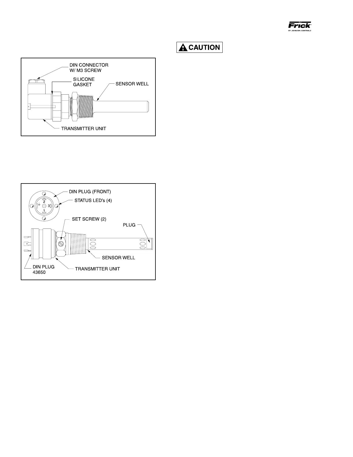
Figure 36 - Oil Level Transmitter
The linear transmitter with hermetic enclosure is based on
the capacitive measuring principle. It features removable
electronics (from the sensor well) eliminating the need to
evacuate the compressor for replacement. This transmitter
is dedicated to oil level control and has no user adjustments.
If it is necessary to replace the well,
the separator must be purged and
the oil drained. Refer to the section
"CHANGING OIL."
1. Shut off control power.
2. Remove DIN connector plug from transmitter.
3. Loosen set screws.
4. Remove transmitter unit.
5. Install new transmitter unit.
6. Tighten set screws.
7. Apply DIN connector plug to transmitter.
8. Turn on control power.
TEMPERATURE and/or PRESSURE
ADJUSTMENT
All temperature and pressure sensors are factory set. If cali-
bration is required, refer to Analog Calibration for tempera-
ture or pressure in QUANTUM
™
LX publication 090-021 O or
090-022 O.
BARE COMPRESSOR MOUNTING
Refer to publication 070-660 SM.