RXF ROTARY SCREW COMPRESSOR UNITS
OPERATION
070.410-IOM (JAN 12)
Page 16
COMPRESSOR OIL COOLING SYSTEMS
The RXF unit can be equipped with one of several systems
for controlling the compressor oil tempera ture. They are
single or dual-port liquid injection, thermosyphon, or water-
cooled oil coolers. Each system is automati cally controlled,
independent of compressor loading or unloading.
Oil cooling systems maintain oil temperature within the fol-
lowing ranges for R-717 and R-22:
Liquid Injection Oil Cooling - 130 - 150°F
External* Oil Cooling - 120 - 140°F
* Thermosyphon Oil Cooling (TSOC) or Water-Cooled Oil
Cooling (WCOC).
SINGLE-PORT LIQUID INJECTION
The single-port liquid injection system is desig ned to permit
liquid refrigerant injection into one port on the compressor
at any given moment and operates as outlined.
The liquid injection solenoid valve is energized by the micro-
processor when the temperature sensor, in stalled in the
compressor discharge, exceeds the setpoint. High-pressure
liquid refriger ant is then supplied to the motorized expansion
valve. Refer to P & I DIAGRAMS section for piping and
instrumentation drawings.
DUAL-PORT LIQUID INJECTION
The dual-port liquid injection system is design ed to obtain
the most efcient compressor performance at high and low
compression ratios by permitting injection of liquid refriger ant
into one of two ports optimally located on the com pressor.
This minimizes the performance penalty incurred with liquid
injection oil cooling.
The dual-port system contains all the com ponents of the
single-port system with the addition of a double-acting
solenoid valve and operates as outlined.
The liquid injection solenoid valve is energized by the
micro processor when the temperature sensor, in stalled in
the compressor discharge, exceeds the setpoint. Liquid
refrigerant is then passed through the motorized expansion
valve to the doub le-acting solenoid valve. Depending on the
compressor’s operating volume ratio (Vi), the micropro cessor
will select the ow of the liquid refrigerant to the optimum
com pressor port.
QUANTUM
™
LX EZ-COOL
™
LIQUID
INJECTION ADJUSTMENT PROCEDURE
Use the following directions to set up and tune the EZ-Cool
™
LIOC with a Quantum
™
LX Control Panel. Also refer to publi-
cation 090-022 O, Quantum
™
LX Operation, for an overview
of PID control.
First, complete calibration of the analog output used for EZ-Cool
™
LIOC. Typically, this will be analog output #1 for PID #1.
• Power down the panel and remove the two control wires
for the valve from terminals 1 & 2 of the P11A terminal
strip of analog board #1.
• Place the leads of a calibrated, quality meter to terminal
one (positive) and terminal two (negative). Set the meter
to read mA DC and power up the panel.
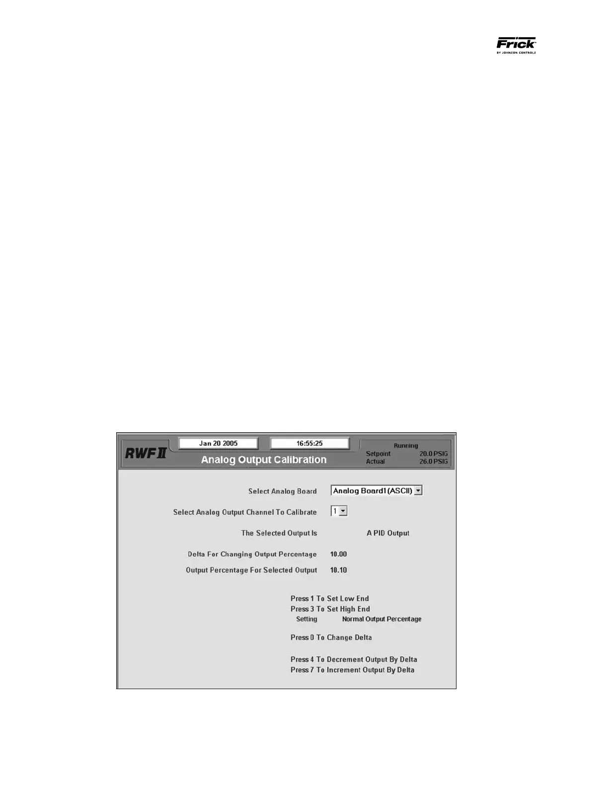
• Set operating session to Session 2 and go to the screen
shown in Figure 21 by pressing [Menu] >[Calibration] >
[Analog Outputs] > [Output Calibration].
Figure 21
• Press [ 1 ] on the keypad to drive the output to the low
end. Using numbers [ 4 ], [ 7 ], and [ 0 ] on the keypad to
increase and decrease the output and change the “Delta
For Changing Output Percentage” setpoint, set the output
to 4mA.
• If the read value is less than the objective of 4 or 20mA
use [ 7 ] on the keypad to increase the output by the
Delta. If the read value is more than the objective, use
[ 4 ] to decrease the value by the Delta.