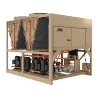
RXF ROTARY SCREW COMPRESSOR UNITS
FORMS
070.410-IOM (JAN 12)
Page 55
Start-up Report Frick Order No: ________________________
Sold To: _______________________________________ Contact Name:__________________________ Date:__________________
End User: ______________________________________ Contact Name:__________________________ Phone:__________________
End User Address: ______________________________________________________________________ Fax No:__________________
City, State, Zip: _________________________________ Start-up Representative _________________
Unit General Information
Unit Model # ___________________________________________ Customer Package Identication # _________________________
Compressor Serial # _____________________________________ Separator National Board # ________________________________
Unit Serial # ____________________________________________ Oil Cooler National Board # _______________________________
Evaporator National Board # _______ Serial # _______________ Condenser National Board # ________ Serial # _______________
Oil Pot National Board # _________________________________ H.P. Receiver National Board # ______
Economizer National Board # _____________________________ Suction Accumulator National Board # ______________________
Refrigerant ______________ Oil Filters ________________ Lube Oil Type _________ Design Operating Conditions
Oil Cooling _____________________________________ ___________
0
Suct. / _________
0
Disch.
Micro Information
Micro Type ________________________ Program Software Ver # _______ and Date __________ UL Serial # __________________
Digital I/O Board #1 Serial # _________________________________ Software Ver # __________and Date ____________________
Digital I/O Board #2 Serial # _________________________________ Software Ver # __________and Date ____________________
Analog Board #1 Serial # ____________________________________ Software Ver # __________and Date ____________________
Analog Board #2 Serial # ____________________________________ Software Ver # __________and Date ____________________
Compressor Motor Starter / Drive Information
Manufacturer __________________________ Part # ___________________ Model # ______________________
Starter Type ____________________________ Serial # _________________________
Input Voltage ______________ Voltage Range ___________ Phase _____________ Hz _____________ Current ____________
Output Voltage ________ Phase ________ Hz _______ Max FLA ________Max LRA ______ Min Load FLA ____ Job FLA _____
Logic Board Serial # __________________ U33 Prog. Ver. ________ Date ___________P/N ________________________
U34 Prog. Ver. ________ Date ___________P/N ________________________
U45 Prog. Ver. ________ Date ___________P/N ________________________
Harmonic Filter Serial # ___________________ Prog. Ver. ________ Date ___________P/N ________________________
Frick Interface Serial # ____________________ Prog. Ver. ________ Date ___________P/N ________________________
CT Location Checked CT Phase ______ CT Ratio ______ Transition Time _________ DBS Ver.# _____________
Oil Pump Information
Pump Mfg. ___________ Model # _________ Serial # ________________ Motor Mfg. _____________ H.P. ________________
Motor RPM __________ Service Factor ______ Volt _______ HZ ______ FLA _____ Design ____ Code _____ Starter Size ______
Cooling Fan Information
Motor HP ______ RPM _________ Service Factor ___________ Volt _______ Hz _________ FLA _______ Cooling Fans _______
Special Options
______________________ ___________________________ _________________________ ________________________
Prestart Checks
Installation, Foundation Compressor PHD Setup Coolant Installed
Position of all valves Motor PHD Setup 4-20 Coolant Loop Pump Setup
Proper oil charge Motor Winding RTD’s Setup Coolant Loop Temp Setup
All wiring connections Motor Bearing RTD’s Setup Cooling Fan Motor I/O Setup
Starter Cleanliness Motor Temperature Thermistor Setup Cooling Fan Rotation Checked
All micro settings 4-20 Motor Drive Signal Calibrated Oil pump motor rotation
4-20 CT Channel 16 Setup Cold alignment Motor rotation
4-20 Output Calibration – Liquid Makeup Valve, Coolant Temp Valve, Economizer Makeup Valve
Conguration
Capacity Channel Direction Package
Mode 1 _____________ ___________ ____________ Compressor ______________
Mode 2 _____________ ___________ ____________ Pump ______________
Mode 3 _____________ ___________ ____________ Dual Pump ______________
Mode 4 _____________ ___________ ____________ Drive ___________________________
VFD Hi & Low PI Control ___________ ____________ Refrigerant __________ K-Factor _________
Miscellaneous Filter _____________________________
Sequencing ________________ PowerPac ____________
Condenser ________________
Screen Saver ________________
 Loading...