Hardware Installation—Installing the IFC-1010/2020
31
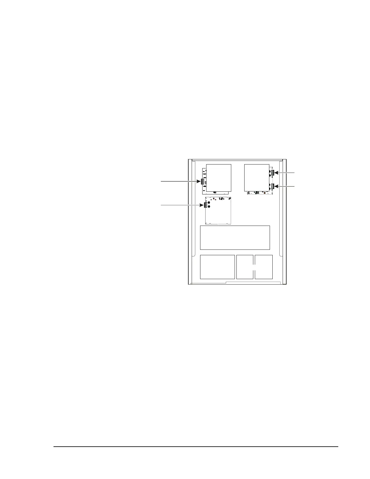
Figure 23 depicts the IFC-1010 with a combination of LIB-400,
LIB-200A, and LIB-200 modules installed in the first and second rows of a
CAB-C3 cabinet.
N34
Two ICA chassis are required, but are not shown in
the figure. The always occupies both addresses (refer to Figure 23) as long
as the following measures are taken:
•
Do not install duplicate loop numbers.
•
When installed in the ICA the LIB-200 always occupies the lower
number address for a given ICA position.
•
Do not install LIB boards in the back right or back left positions of the
second row.
•
Do not install LIB boards in row three.
Loop 1
(LIB-200)
Loop 3
(LIB-200A installed in
left front position of ICA.)
libmix10
SIB CPU
MPS-24A
or
MPS-24AE
Batteries
CHS-4/4L
A B C D
Loop 4 (LIB-400)
Loop 2 (LIB-400)
Figure 23: LIB Placement Example in an IFC-1010
N34