5808011-JIM-A-0320
Johnson Controls Ducted Systems 67
Adjusting the temperature rise
The temperature rise is the difference of temperature between
the return air and the heated air from the furnace. The
temperature rise must lie within the range shown on the CSA
rating plate and the data in Table 12.
1. After about 20 minutes of operation, determine the furnace
temperature rise. Take readings of both the return air and
the heated air in the ducts (about 6 feet from the furnace)
where they are not affected by radiant heat.
2. After you determine the temperature rise, calculate the
CFM according to the following formula.
3. Increase the blower CFM to decrease the temperature rise.
Decrease the blower CFM to increase the rise (see Supply
air drive adjustment on page 58).
Note: Each gas heat exchanger size has a minimum
allowable CFM. Below this CFM, the limit opens.
Inspecting and servicing burners and orifices
1. Open the union fitting just upstream of the unit gas valve
and downstream from the main manual shut-off valve in
the gas supply line.
2. Remove the screws that hold each end of the manifold to
the manifold supports.
3. Disconnect the wiring to the gas valves and spark igniters.
4. Remove the manifold and gas valve assembly. Inspect the
orifices and replace them if required.
5. To service the burners, remove the heat shield on top of
the manifold supports. Inspect the burners and replace
them if required.
6. Reverse the above procedure to replace the assemblies.
Verify that burners are level and seated at the rear of the
gas orifice.
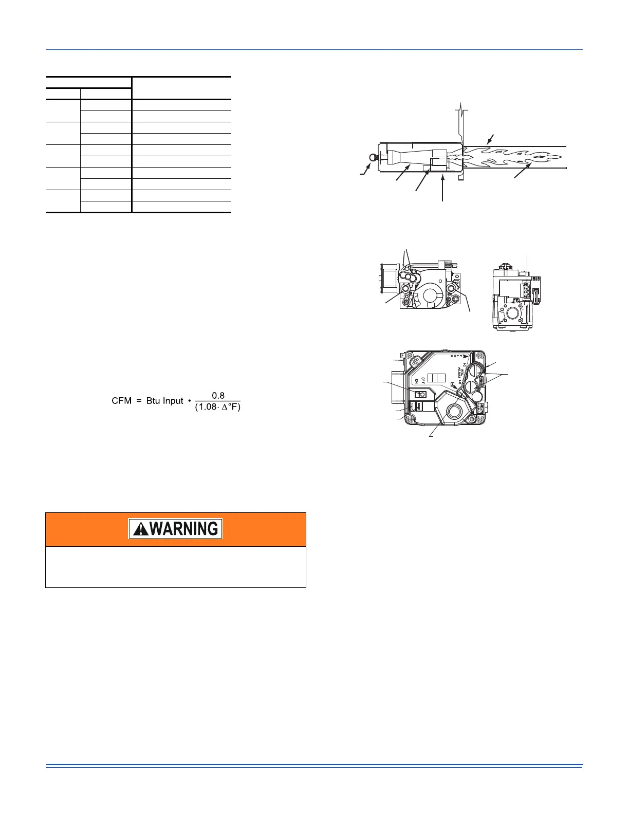
Figure 29: Typical flame
Figure 30: Typical two stage gas valve
Navigation components for the Smart
Equipment™ control board
The following components are needed to access the control
points in the Smart Equipment™ control. Installation and
operation guides are available from your equipment dealer or
distributor.
1. Local LCD on the unit control board.
2. Mobile Access Portal (MAP) Gateway (portable).
• Source 1 P/N S1-JC-MAP1810-OP
3. MAP Gateway Quick Start Guide P/N 24-10737-16
4. MAP Gateway Instruction P/N 24-10737-8
For more information on the Smart Equipment™ unit control board
navigation, refer to the Smart Equipment™ Quick Start Guide.
Note: For more in-depth sequence of operation of the Smart
Equipment™ control, refer to the Smart Equipment™
Controls Sequence of Operation Overview LIT-
12011950.
Table 29: Gas heat limit control settings
1
1. Roll-out = 300°F, Auxiliary limit = 200°F
Unit
Main limit setting °F
Size Option
06
N12 165
N18 165
07
N12 165
N18 165
08
N12 215
N18 195
10
N18 195
N24 160
12
N18 195
N24 160
Before you check or change burners, pilot, or orifices,
close the main manuals shut-off valve and turn off all
electrical power to the unit.
HEAT EXCHANGER TUBE
BURNER FLAME
(BLUE ONLY)
IGNITOR
BURNER BRACKET
BURNER
GAS
SUPPLY
PIPE
INLET
PRESSURE
TAP
HIGH & LOW GAS ADJUSTMENT
OUTLET
PRESSURE
TAP
HI
LO
ON
OFF
MATE-N-LOCK
CONNECTORS
MV
C
HI
REGULATOR COVER SCREWS
(REG. ADJ. BENEATH THESE
SCREWS)
TERMINAL – HI (2ND STAGE)
ON/OFF SWITCH
C
MP
OUTLET PRESSURE TAP
INLET PRESSURE TAP
OR
TERMINAL – MP (1ST STAGE)
TERMINAL – C (COMMON)

 Loading...


