5808011-JIM-A-0320
Johnson Controls Ducted Systems 7
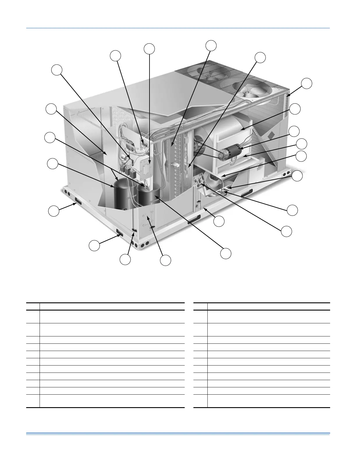
Figure 4: Component location
Figure 4 shows the J10ZB model. Table 1 lists the components of the unit.
Table 1: Component location table
Item Description Item Description
A Terminal block for high-voltage connection L
Two-stage gas heating to maintain warm, comfortable
temperature
B
Smart Equipment™ control board with screw connector for thermostat
wiring and network connections
M Intelligent control board for safe and efficient operation
C Disconnect location (optional disconnect switch) N Slide out drain pan with 1 inch NPT, female connection
D Filter access (2 in. or 4 in. filter options) O Compressor #1 access
E Filter drier (solid core) P Side entry power and control knockouts
F Micro-channel aluminum tube/aluminum fin condenser Q Toolless door latch
G Slide-out motor and blower assembly for easy adjustment and service R Roof curbs in eight-inch and fourteen-inch heights
1
1. Roof curbs for transitioning from York Sunline™ footprint to the ZB Series footprints are also available (field-installed accessory).
H Belt-drive blower motor S Base rails with forklift slots (three sides) and lifting holes
I VFD Location T Compressor #2 access
J Power ventor motor U Three stage cooling for maximum comfort
K
20-gauge aluminized steel tubular heat exchanger for long life
(stainless steel option)
V Second model nameplate inside hinged access panel
A
G
H
I
J
K
L
M
N
O
P
Q
R
S
T
U
B
C
D
E
F
V

 Loading...


