WARNING
This is not a backseating valve. The service access
port has a valve core. Opening or closing valve does
not close service access port. If the valve stem is
backed out past the chamfered retaining wall, the
O-ring can be damaged causing leakage or system
pressure could force the valve stem out of the valve
body possibly causing personal injury.
The valve can be opened by removing the service valve
cap and fully inserting a hex wrench into the stem and
backing out counter-clockwise until valve stem just
touches the chamfered retaining wall.
Connecting the refrigerant lines
1. Remove the cap and Schrader core from both the
liquid and vapor service valve service ports at the
outdoor unit. Connect low pressure nitrogen to the
liquid line service port.
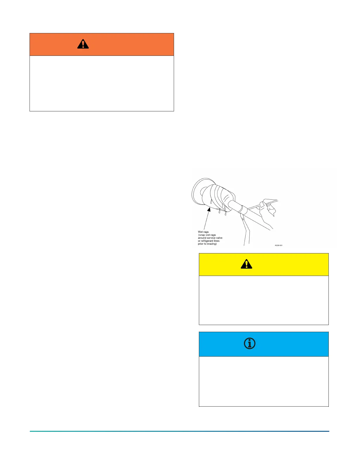
2. Braze the liquid line to the liquid valve at the
outdoor unit. Be sure to wrap the valve body with a
wet rag. Allow the nitrogen to continue flowing.
3. Carefully remove the plugs from the indoor liquid
and vapor connections at the indoor coil.
4. Braze the liquid line to the indoor coil liquid
connection. Nitrogen should be flowing through
the indoor coil.
5. Slide the grommet away from the vapor connection
at the indoor coil. Braze the vapor line to the
indoor coil vapor connection. After the connection
has cooled, slide the grommet back into original
position.
6. Protect the vapor valve with a wet rag and braze
the vapor line connection to the outdoor unit.
The nitrogen flow should be exiting the system
from the vapor service port connection. After this
connection has cooled, remove the nitrogen source
from the liquid fitting service port.
7. Replace the Schrader core in the liquid and vapor
valves.
8. See Indoor expansion device.
9. Leak test all refrigerant piping connections
including the service port flare caps to be sure they
are leak tight. Do not over-tighten (between 40 in.
lb and 60 in. lb maximum).
10. Evacuate the vapor line, indoor coil, and liquid line
to 500 microns or less. See SECTION V: Evacuation.
11. Release the refrigerant charge into the system.
Open the liquid line service valve first. Once system
pressures have equalized, open the vapor line
service valve. Valves can be opened by removing
the valve caps and turn the valve counterclockwise
using a hex head wrench. If the service valve is a
ball valve, use an adjustable end wrench to turn
valve stem one-quarter turn counterclockwise
to open. Do not overturn or the valve stem may
break or become damaged. See Precautions during
brazing of service valve.
12. Replace service valve cap finger tight, then tighten
an additional 1/12 turn (1/2 hex flat). Cap must be
replaced to prevent leaks.
13. See System charge for checking and recording
system charge.
Example:
Figure 5: Heat protection
CAUTION
Do not install any coil in a furnace which is to
be operated during the heating season without
attaching the refrigerant lines to the coil. The
coil is under pressure which must be released
to prevent excessive pressure build-up and
possible coil damage.
NOTICE
Line set and indoor coil can be pressurized to
250 psig with dry nitrogen and leak tested with
a bubble type leak detector. Then release the
nitrogen charge.
Do not use the system refrigerant in the outdoor
unit to purge or leak test.
R-410A Outdoor Split-System Heat Pump Installation Manual - YH2E / THE2 / RHP143 Series 11
Johnson Controls Ducted Systems
 Loading...


