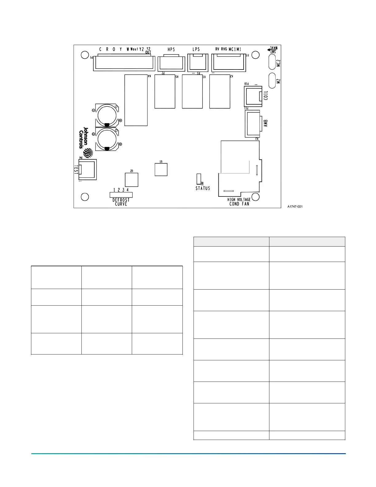
Figure 22: Demand defrost control module
Fault code display
The control shall provide status codes using the LED.
Status codes indicate the state of operation of the unit but
do not represent a fault. The table below describes the
LED displayed during status codes. Status codes will not
be displayed when a fault code is present.
Table 47: Status code display
No power to the
control
No faults active
Nothing
energized
OFF
Compressor
operation active
No faults active
M energized
ON
Control normal
operation –
no call for
compressor
No faults active
Y not present
2 s ON/2 s OFF
Control normal
operation – in
ASCD period
No faults active,Y
present, ASCD
timer not expired
0.1 s ON/0.1 s
OFF
The control shall provide fault codes using the Status LED.
Table 48 describes the LED displays during fault codes.
Unless otherwise specified, the control shall provide
flashes that are a 1/3 s on and 1/3 s off for fault codes.
The control shall only display a single fault code on the
LED. The control shall display the fault code on the LED
repeatedly with a 2 s off period between repetitions of the
fault code. If multiple fault codes are present at the same
time, the LED shall display only the most recent fault.
Table 48 shows the number of flashes for the specified
code. For instance, a flash code entry of 3 indicates that
the control energizes the output for three 1/3 s on, 1/3 s
off flashes, waits 2 s, then energizes the output for three
more 1/3 s on, 1/3 s off flashes and repeats.
Table 48: Faults
Description STATUS LED
High-pressure switch fault
(not in lockout yet)
2 Flashes
System in high-pressure
switch lockout (last mode
of operation was normal
compressor)
3 Flashes
System in high-pressure
switch lockout (last mode
of operation was defrost)
4 Flashes
System in low-pressure
switch lockout (last mode
of operation was normal
compressor)
5 Flashes
Low voltage (<19.2 VAC)
preventing further relay
outputs for > 2 s
6 Flashes
Low voltage (<16 VAC)
stopped current relay
outputs for > 2 s
7 Flashes
Coil sensor failure (open or
shorted) - Comp. allowed/
lockout
8 Flashes
Outdoor ambient sensor
failure (open or shorted) -
Compressor allowed if coil
is > 32°F
9 Flashes
Control failure 10 Flashes
R-410A Outdoor Split-System Heat Pump Installation Manual - YH2E / THE2 / RHP143 Series 35
Johnson Controls Ducted Systems
 Loading...


