the control allows another defrost cycle when needed. The
timer is based on accumulated compressor runtime.
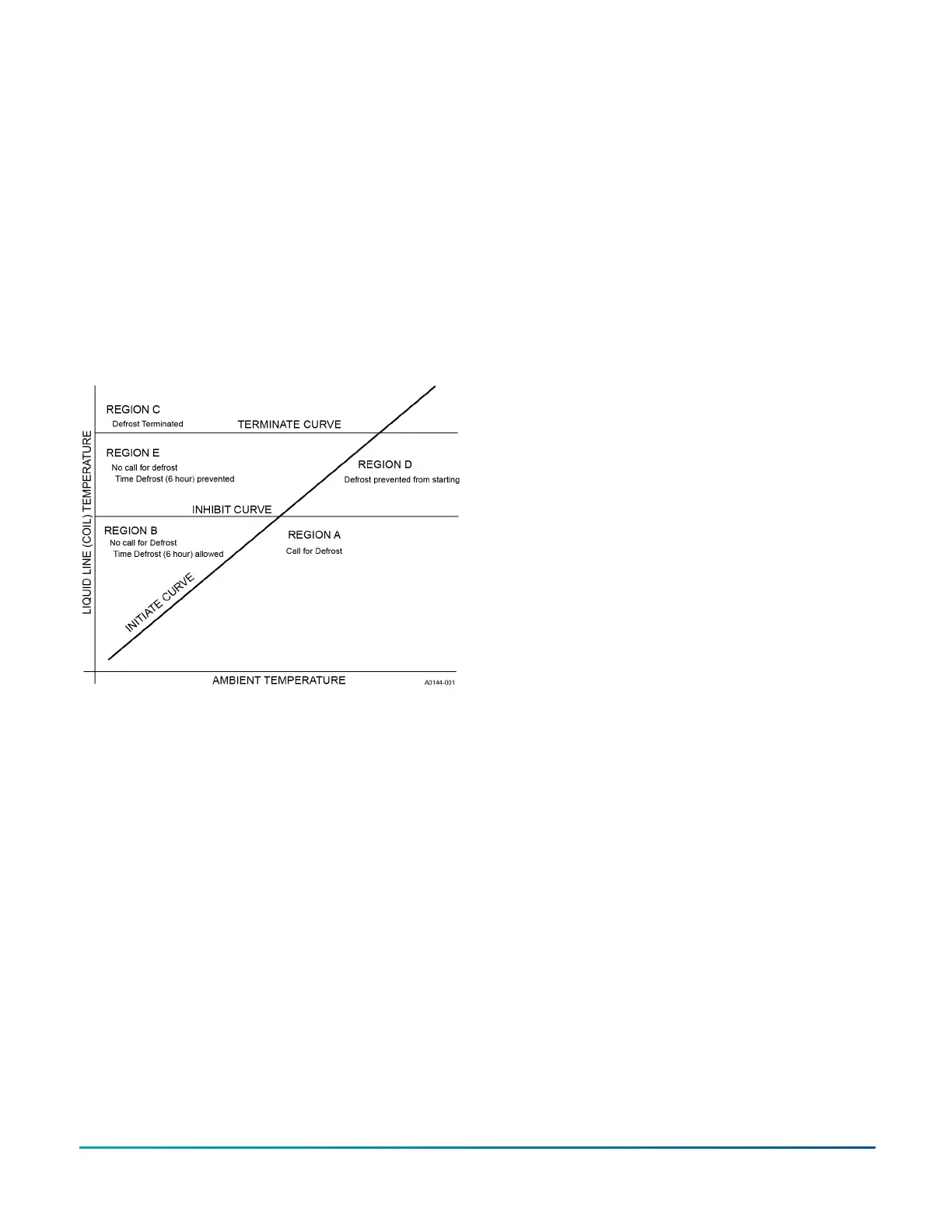
Defrost termination
The control terminates the defrost cycle immediately
after the liquid line temperature reaches the terminate
temperature or after 14 min of defrost operation. See
Figure 23.
The control does the following to terminate a defrost
cycle:
• Energize the outdoor fan.
• De-energize the reversing valve.
• De-energize the auxiliary heat output through the W
out terminal.
• Reset and restart the 40 min defrost inhibit timer.
Figure 23: Defrost operation curves
Cooling operation
During cooling operation, the control receives thermostat
signals at the Y (Y + Y2 for 2nd stage), and O input
terminals. The control energizes the M (M + M2 for
2nd stage) compressor output terminal. This signal
energizes the coil of the compressor contactor causing
the compressor to operate. The control also delivers
power to the COND FAN terminals causing the outdoor
fan to operate. The control energizes the REV VALVE
terminal with 24 VAC to switch the reversing valve.
Heating operation
During normal heating mode, the control receives a
thermostat signal at the Y (Y + Y2 for 2nd stage) input
terminal. The control energizes the M (M + M2 for
2nd stage) compressor output terminal. This signal
energizes the coil of the compressor contactor causing
the compressor to operate. The control also delivers
power to the COND FAN terminals causing the outdoor
fan to operate. The reversing valve is not energized in
heating mode.
In low ambient conditions (<40°F) the control energizes
M2 and Y2 out, forcing second stage operation for the
remainder of the call.
Emergency heat
When the thermostat calls for emergency heat operation
(W signal without a Y signal), the control energizes the
Wout terminal immediately.
Pressure switch fault and lockout
The heat pump is equipped with a high pressure switch
and low pressure switch that connect to the control at
the pressure switch terminals. If the high pressure switch
input opens for more than 40 ms, the control de-energizes
the compressor. If the switch is closed and a thermostat
call for compressor operation is present, the control
applies the 5 min anti-short-cycle delay timer and starts
the compressor when the timer expires.
If the low pressure switch opens for 5 s under conditions
when the control is not ignoring the low pressure switch
input, the control will enter a low pressure switch fault.
The control ignores the low pressure switch input during
the following conditions:
• Defrost operation
• The first 120 s of compressor operation
• 120 s following the completion of a defrost cycle
• When the outdoor ambient temperature is below 5
°F
When the compressor starts following a switch fault,
the control starts a 6 h timer based on accumulated
compressor runtime. If the control senses another
opening of the switch before the timer expires, it causes a
soft lockout condition. The second opening of the switch
must be greater than 160 ms for the lockout to occur. If
the second opening is between 40 ms and 160 ms, the
control de-energizes the compressor but does not cause
a soft lockout condition. If the control does not sense a
second switch opening before the 6 h timer expires, the
timer and counter reset.
During the soft lockout mode, the control de-energizes
the compressor and energizes the LED output with the
appropriate flash code.
The control resets the soft lockout condition when any of
the following occur after removal of the fault condition:
• Power is cycled to the R or Y inputs of the control.
This causes the soft lockout condition to be reset
when the thermostat is satisfied or when the
thermostat is set to SYSTEM OFF and back to HEAT or
COOL mode.
• The TEST terminals short for more than 2 s.
When the soft lockout condition is reset, the control stops
displaying the fault code and responds to thermostat
inputs normally.
Instructing the owner
Assist the owner with processing warranty cards or online
registration. Review the User’s Information Manual, and
provide a copy to the owner and guidance on correct
operation and maintenance. Instruct the owner or the
operator how to start, stop, and adjust the temperature
setting.
When applicable, instruct the owner that the compressor
is equipped with a crankcase heater to prevent the
migration of refrigerant to the compressor during the
R-410A Outdoor Split-System Heat Pump Installation Manual - YH2E / THE2 / RHP143 Series 37
Johnson Controls Ducted Systems
 Loading...


