NOTICE
Flexible electrical wiring must be installed in order to
use the swing away function of the control box. Rigid
type electrical connections require the wiring to be
disconnected in order to swing the control box open.
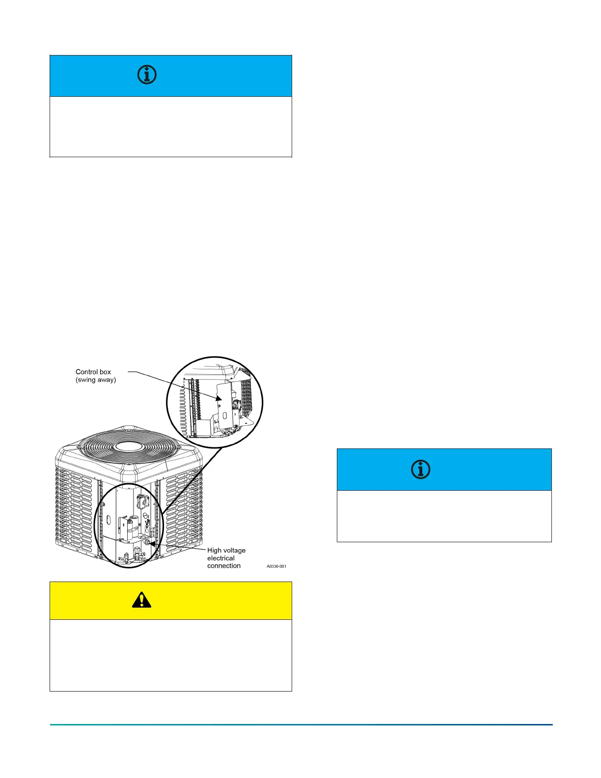
The control box can then swing open from the left by
rotating on the right side pivots for easy service of
refrigeration components. If no wiring is in or routed
through the control box, it can be removed from the
unit by lifting slightly, tilting the top hinge out, and
lifting the bottom hinge out. During the installation, it
is recommended to route the low voltage wiring for the
thermostat along the unit high voltage wiring to help
facilitate the swing away feature of the control box. See
Figure 9.
Check the electrical supply to be sure that it meets the
values specified on the unit nameplate and wiring label.
Power wiring, control (low voltage) wiring, disconnect
switches and over current protection must be supplied
by the installer. Wire size should be sized per NEC
requirements.
Figure 9: Outdoor unit swing away control box
CAUTION
All field wiring must use copper conductors only and
be in accordance with Local, National, Fire, Safety
and Electrical Codes. This unit must be grounded with
a separate ground wire in accordance with the above
codes.
The complete connection diagram and schematic wiring
label is located on the inside surface of the unit service
access panel.
Field connections power wiring
1. Install the correct size weatherproof disconnect
switch outdoors and within sight of the unit.
2. Remove the screws at the top and sides of the
corner cover. Slide the control box cover down and
remove from unit.
3. Run power wiring from the disconnect switch to the
unit.
4. Route wires from disconnect through power wiring
exit provided and into the unit control box correct
location as shown in Figure 10, Figure 11, or Figure
12.
5. Install the correct size time-delay fuses or circuit
breaker, and make the power supply connections.
Field connections control wiring
1. Route low voltage wiring into bottom of control box
correct location as shown in Figure 10, Figure 11,
and Figure 12. Connect low voltage wiring to the
appropriate connections. Reference Figure 13 to
Figure 20 depending on the application.
2. The complete connection diagram and schematic
wiring label is located on the inside surface of the
unit service access panel.
3. Replace the control box cover removed in Step 2 of
the Field connections power wiring procedure.
4. All field wiring to be in accordance with national
electrical codes (NEC) and local-city codes.
NOTICE
A Start Assist Kit is available and
recommended for long lineset applications or
in areas of known low voltage problems.
5. Mount the thermostat about 5 ft above the floor,
where it will be exposed to normal room air
circulation. Do not place it on an outside wall or
where it is exposed to the radiant effect from
exposed glass or appliances, drafts from outside
doors or supply air grilles.
6. Route the 24 V control wiring (NEC Class 2) from
the outdoor unit to the indoor unit and thermostat.
R-410A Outdoor Split-System Heat Pump Installation Manual - YH2E / THE2 / RHP143 Series28
Johnson Controls Ducted Systems
 Loading...


