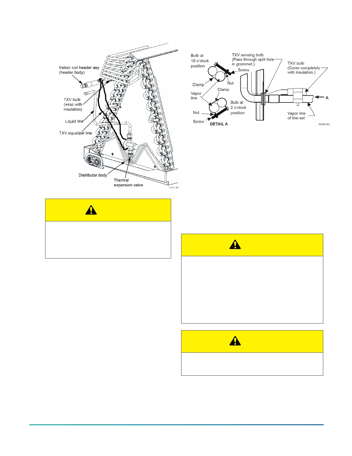
Figure 7: TXV bulb and equalizer line installations
CAUTION
In all cases, mount the TXV bulb after vapor
line is brazed and has had sufficient time to
cool. Failure to use suction line grommet may
result in premature TXV failure.
7. If the indoor coil is an A coil, skip to Step 8. If not,
pass the TXV temperature sensing bulb through
the suction line split grommet in the access panel.
8. Install the TXV bulb to the vapor line using the bulb
clamps furnished with the TXV assembly. Ensure
the bulb is making maximum contact. See Figure 7
and Figure 8.
a. If possible, install the temperature bulb on
a horizontal run of the vapor line. Ensure
that the bulb is installed at a 10 o’clock or 2
o’clock position. See Figure 8.
b. If bulb installation is made on a vertical run,
ensure that the bulb is a minimum of 8 in.
(20.3 cm) away from the elbow coming out
of the coil. Position the bulb with the tail of
the bulb at the top, so that the bulb acts as a
reservoir.
c. Insulate the bulb using thermal insulation
provided to protect it from the effect of the
surrounding ambient temperature. Cover
completely to insulate.
9. After line set is installed, leak test the system.
Figure 8: Proper bulb location
Evacuation
It will be necessary to evacuate the system to 500 microns
or less. If a leak is suspected, leak test with dry nitrogen to
locate the leak. Repair the leak and test again.
To verify that the system has no leaks, close the valve to
the vacuum pump suction to isolate the pump and hold
the system under vacuum. Watch the micron gauge for
a few minutes. If the micron gauge indicates a steady
and continuous rise, it is an indication of a leak. If the
gauge shows a rise, then levels off after a few minutes
and remains fairly constant, it is an indication the system
is leak free but still contains moisture and may require
further evacuation if the reading is above 500 microns.
System charge
CAUTION
If a field installed device is placed in the inner-
connecting refrigerant lines that can store a significant
refrigerant charge (for example, a refrigerant mass
flow meter or a liquid receiver), the unit may not
perform as designed. If such a performance-affecting
device is installed and it is possible to check the
unit in heating mode, the unit pressures should be
confirmed in heating mode. See the heating charging
charts located in this installation manual.
CAUTION
Refrigerant charging should only be carried out by a
licensed qualified air conditioning contractor.
To ensure that the unit performs at the published levels,
it is important to determine the indoor airflow and add
refrigerant charge accordingly.
R-410A Outdoor Split-System Heat Pump Installation Manual - YH2E / THE2 / RHP143 Series 13
Johnson Controls Ducted Systems
 Loading...


