542933-UIM-D-0513
Johnson Controls Unitary Products 27
Heat Kit Configuration
This screen is available if there is a variable speed air handler with the addition of an approved heat
kit. Here the heat kits approved for the installed air handler will be displayed (and the current
selected heat kit will be highlighted). If there has been a change in the originally installed heat kit,
the installer MUST use this screen so that the appropriate air flows will be applied during heat kit
operation.
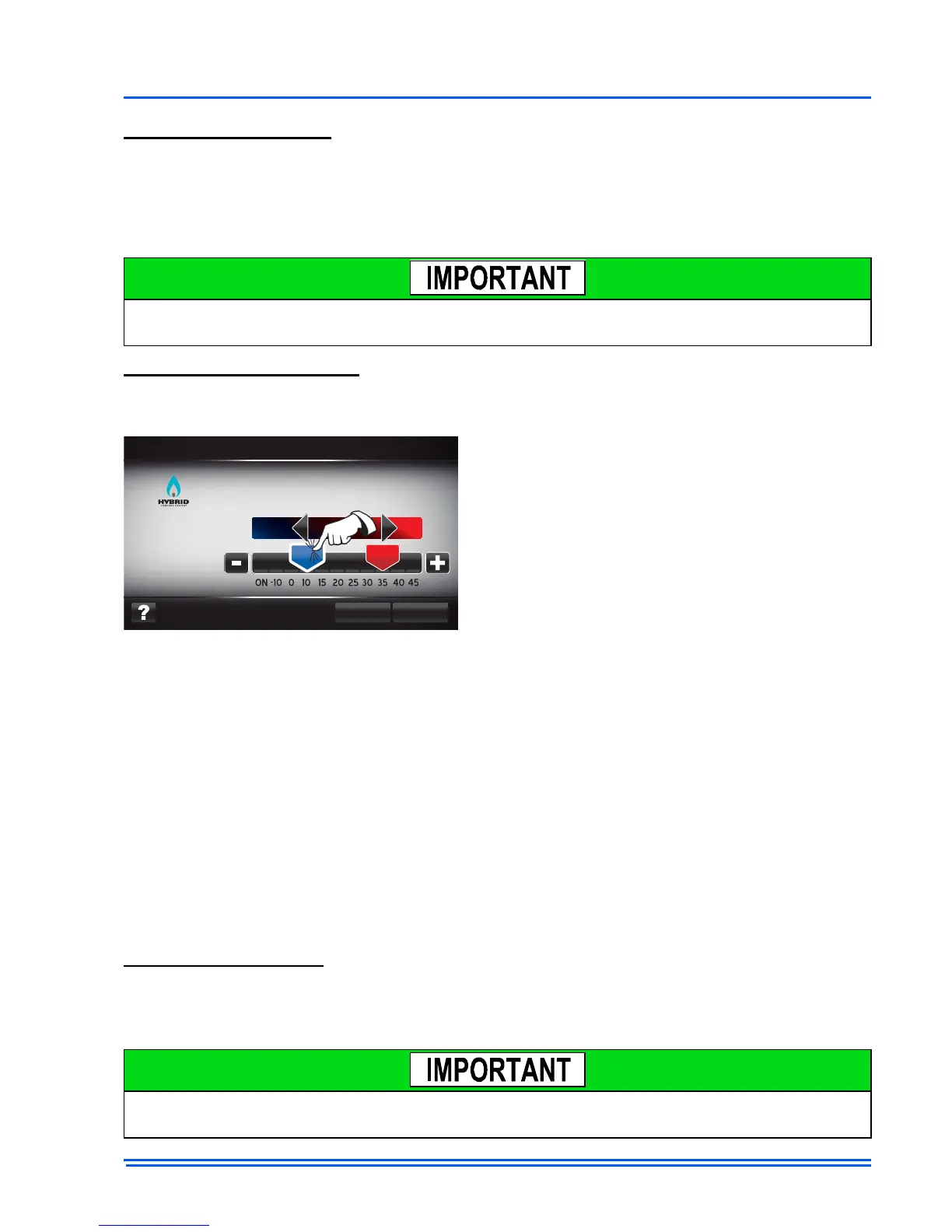
Heat Pump Configuration
These screens are available if there is a communicating heat pump control installed. These screens
allow heat pump “jumpers” to be changed from the Touch Screen Communicating Control.
If the outdoor temperature is above the balance point temperature setting, the auxiliary heat will not
be used to satisfy the heating demand *.
If the outdoor temperature is below the LTCO, the heat pump will not be used to satisfy the heating
demand.
If the outdoor temperature is between both the balance point and the LTCO temperature settings,
the thermostat will stage both heat pump and auxiliary heat as demand increases.
*If after 4 hours the heating demand is not satisfied, auxiliary heat will be supplied. Reference
communicating heat pump literature for more detail on heat pump operation.
Airflow Configuration
The airflow configuration screens are available on systems that contain a communicating ID unit.
Here the user can change delay profiles and airflow settings. CFM settings and ranges are defined
by factory programmed values in the outdoor and indoor controls.
If the heat kit selected does not match the heat kit installed, the Touch Screen Communicating
Control may apply air flow values that can cause nuisance limit trips or cold blow.
Compressor Delay: (ON, OFF) Compressor
Delay will turn the compressor off for 30 seconds
immediately after energizing the reversing valve
(in defrost). The purpose is to reduce noise in
defrost.
Defrost Curve: (1-6) Defrost Curve is set in the
factory and should only be changed in a repair
part installation
Switch Point: (35, 40, 45) Switch Point is the temperature of the liquid line sensor (in Fahrenheit)
at which the heat pump will force 2
nd
stage operation.
Y2 Lock: (ON, OFF) Y2 Lock allows the Heat pump control to anticipate 2
nd
stage operation.
Balance Point and Low Temperature Cut Out (LTCO): Balance Point and LTCO settings deter-
mine how heating calls will be satisfied by the system.
Changing airflow settings can effect system efficiency. Reference outdoor equipment tech guide
for more information on system efficiencies.
 Loading...