System 450™ Series Control Module with Ethernet Communications Installation Instructions
14
Setting Up Outputs That Reference a P 110 Sensor
The P 110 Sensor Type can monitor negative pressure down to 20 InHg (-10 psi). When referencing a P 110
sensor, System 450 displays negative pressure values in InHg on the Main and System Status screens.
But when you set up an output that references a P 110 sensor and the setup value is a negative pressure value,
you must select a pressure value in negative psi.
Use Table 6 to determine the negative PSI setup value that corresponds to your InHg target value. For example, if
you want a relay output to go off when the sensed pressure reaches 7 InHg, you select the value -3.5 (psi) in the
output’s Relay OFF Selection screen.
Note: When an output references the P 110 Sensor Type and the output is set up for Differential Control (Sn-1
and Sn-2 are P 110 Sensor Type), the negative pressure values displayed in the differential pressure System
Status screen (dIFP) appear as negative psi values, not InHg values. See Differential Control
for more information.
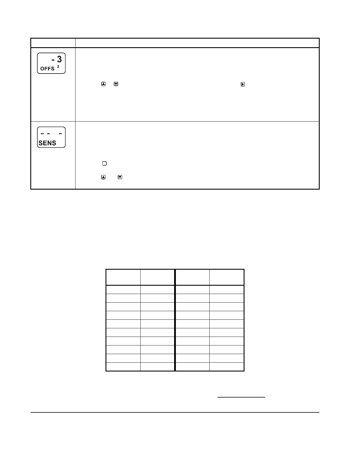
Temperature Offset Selection Screens: Select a temperature offset for the temperature inputs (only) in
your control system.
Sensor Type °F enables an offset of +/- 5°F in 1 degree increments.
Sensor Type °C enables an offset of +/- 2.5°C in 0.5 degree increments.
Note: The temperature offset changes the displayed temperature value by the selected offset value.
5. Press or to select the desired temperature offset value. Press :
• to go to the next Temperature Offset Selection screen (if there are additional temperature sensors in
your control system) and repeat this step for each temperature sensor.
• to return to the Sensor Setup Start screen.
The screen example shows an OFFS value of -3 (°F) for Sensor 2. Therefore, a sensed temperature
value of 75 (°F) at Sensor 2 is displayed as 72 (°F).
Sensor Setup Start Screen: When you have finished setting up all of the sensors for your control
system, the display returns to the Sensor Setup Start screen.
Note: You can edit the sensor setup values at any time, if required. However, changing the Sensor Type
for a sensor that is referenced by an output requires setting up the output again to the new Sensor Type
values.
After the sensors are set up for your control system, you can:
• Press to scroll through the Output Setup Start screens and begin setting up your system
outputs.
• Press and simultaneously to return to the Main screens.
The screen example shows Sensors Setup Start screen with flashing dashes.
Table 6: InHg Target Values and PSI Setup Values
InHg
Value
psi Setup
Value
InHg
Value
psi Setup
Value
1 -0.5 11 -5.5
2 -1.0 12 -6.0
3 -1.5 13 -6.5
4 -2.0 14 -7.0
5 -2.5 15 -7.5
6 -3.0 16 -8.0
7 -3.5 17 -8.5
8 -4.0 18 -9.0
9 -4.5 19 -9.5
10 -5.0 20 -10.0
Table 5: System 450 Sensor Setup Screen Information and Procedures (Part 2 of 2)
LCD Screen Name, Description or Function, User Action, and Example
M
 Loading...


