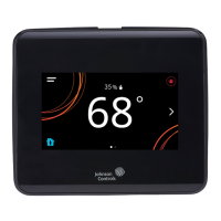
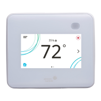
TEC3000 Series Networked and Wireless Proportional Fan Coil and
Individual Zone Thermostat Controllers with Dehumidification Capability
Quick Start Guide
1
Refer to the QuickLIT website for the most up-to-date version of this document.
North American emissions compliance
United States
Canada
Installation
Parts included
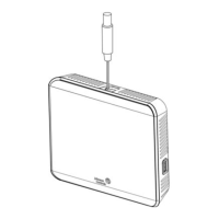
• One TEC3000 Series Thermostat Controller with integral mounting base
• One installation instructions sheet
Location considerations
For networked models, locate the TEC3000 Series Thermostat Controller:
• On a partitioning wall, approximately 5 ft (1.5 m) above the floor in a location of average temperature, allowing
for vertical air circulation to the TEC
• Away from direct sunlight, radiant heat, outside walls, outside doors, air discharge grills, stairwells, and
from
b
ehind doors
• Away from steam or water pipes, warm air stacks, unconditioned areas (not heated or cooled), or sources of
electrical interference
• In a clear path between the integrated passive infrared (PIR) occupancy sensor (if equipped) and the spac
e
be
ing monitored
This equipment has been tested and found to comply with the limits for a Class B digital device, pursuant to Part
15 of the FCC Rules. These limits are designed to provide reasonable protection against harmful interference in
a residential installation. This equipment generates, uses and can radiate radio frequency energy and, if not
installed and used in accordance with the instructions, may cause harmful interference to radio communications.
However, there is no guarantee that interference will not occur in a particular installation. If this equipment does
cause harmful interference to radio or television reception, which can be determined by turning the equipment off
and on, the user is encouraged to try to correct the interference by one or more of the following measures:
• Reorient or relocate the receiving antenna.
• Increase the separation between the equipment and receiver.
• Connect the equipment into an outlet on a circuit different from that to which the receiver is connected.
• Consult the dealer or an experienced radio/TV technician for help.
This Class (B) digital apparatus meets all the requirements of the Canadian Interference-Causing Equipment
Regulations.
Cet appareil numérique de la Classe (B) respecte toutes les exigences du Règlement sur le matériel brouilleur
du Canada.
TEC3000 Series Networked and Wireless Proportional Fan
Coil and Individual Zone Thermostat Controllers with
Dehumidification Capability
Quick Start Guide
TEC3322-1x-xxx, TEC3323-1x-xxx, TEC3622-1x-xxx, TEC3623-1x-xxx, TEC3022-1x-xxx, TEC3023-1x-xxx
Part No. 24-11353-00028, Rev.
C
Issued May 2019
(barcode for factory use only)
24-11353-00028, Rev. C
*241135300028C*