VA9310 Series Electric Non-Spring Return Valve Actuators Installation Instructions
3
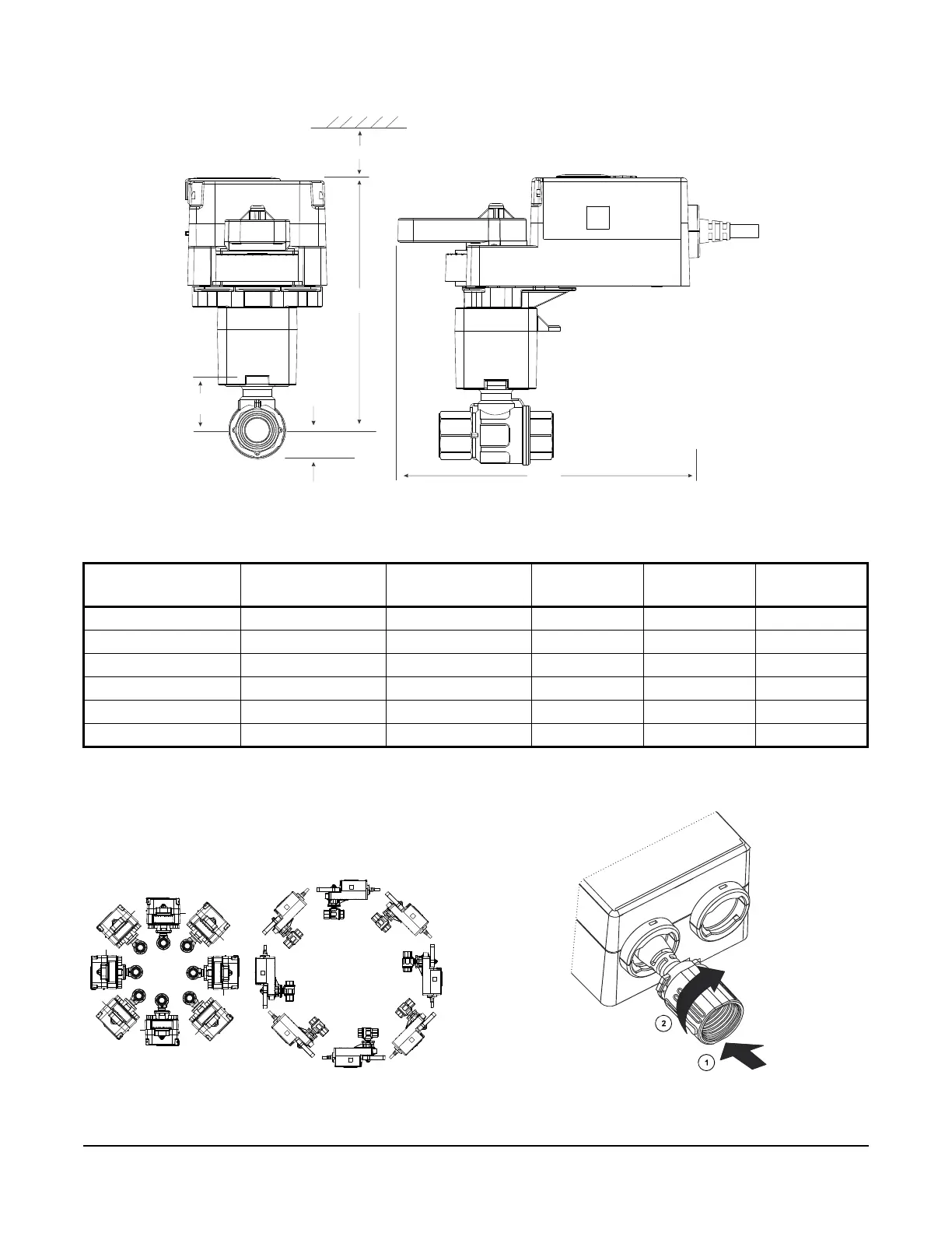
Dimensions
Mounting
You can mount the VA9310 actuator directly to the
valve for preferred performance or with the M9000-561
thermal barrier when high-temperature fluid is used or
additional spacing for insulation is needed.
Installing the Conduit Connector
1. Slide the connector onto the actuator.
2. Turn the connector and lock it into position.
Table 2: VA9310-HGA-2 Actuated VG1241, VG1245, VG1841, and VG1845 Series Ball Valve Dimensions,
in. (mm)
Valve Size, in. (DN) A (With Thermal
Barrier)
A (Without
Thermal Barrier)
BCD
1/2 (DN15) 5-3/4 (146) 4-3/8 (111) 21/32 (17) 1-7/32 (31) 6-13/32 (163)
3/4 (DN20) 5-3/4 (146) 4-3/8 (111) 21/32 (17) 1-7/32 (31) 6-13/32 (163)
1 (DN25) 5-13/16 (148) 4-7/16 (113) 3/4 (19) 1-5/16 (33) 6-13/32 (163)
1-1/4 (DN32) 6-1/4 (159) 4-7/8 (124) 1-1/32 (26) 1-23/32 (44) 6-13/32 (163)
1-1/2 (DN40) 6-13/32 (163) 5-1/32 (128) 1-1/8 (29) 1-7/8 (48) 6-13/32 (163)
2 (DN50) 6-5/8 (168) 5-1/4 (133) 1-15/32 (37) 2-1/16 (53) 6-13/32 (163)
Figure 1: Valve and Actuator Dimensions (With Optional M9000-561 Thermal Barrier)
3-1/2 in. (89 mm)
C
Optional
Thermal
Barrier
Optional
Thermal
Barrier
Figure 2: Mounting Positions
X
X
X
X
X
X
FIG:Actuator position
FIG:Adding Conduit Connector
 Loading...


